This thread has been locked.

If you have a related question, please click the "Ask a related question" button in the top right corner. The newly created question will be automatically linked to this question.

CC3220MOD: First time boot issues

Part Number: CC3220MOD

I'm trying to find the root cause of a first time boot issue we are seeing with the CC3220MODSF on our boards.

Summary: The board is assembled with an unprogrammed module. In production test the serial flash (in the module) is the programmed while reset is kept active low and when the programming is done the reset is de-asserted. After a delay to allow the module to boot, some commands are sent to the Wi-Fi module to check that it's alive. For simplified testing I have used two commands, one to read out the MAC address and one to Clock_getTicks() done in a loop with some delay between each operation. It's then a finite probability that Wi-Fi module will not respond. Meaning running the same test 100 times on a board a variable percentage of the tests will fail.

More details:

The serial flash is programmed through SPI as described in chapter 4 in swra568. The programming is done through test needles. When the programming is done the buffer is set in high-z.

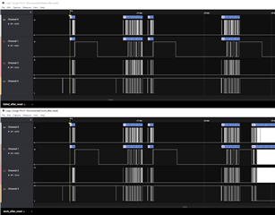
 I have monitored the SPI bus when the reset to the module is de-asserted.  Channel0 is flash_spi_clk and channel1 is  reset. This is typically happens when the module is not responding:

The SPI bus is active for 2.5 ms meaning that the content of the serial flash is never read.

For this cases I found that doing an extra reset helps:

The first 2.5 ms on the SPI bus is exactly the same as for the first picture. The SPI bus pulses seen after first time boot is when the MAC address is read out. The "Clock_getTicks()" will return 0x6 every second time.

Inserting a 3. reset:

the module returns an expected Clock_getTicks() value each time it's called and no traffic on the SPI bus when reading out the MAC address. 

Could someone explain why the Wi-Fi module needs an extra reset to boot in some cases? If the reset time is too short it also fails. 

  • Hi TheGhostOf,

    I will follow up here on Monday. In the meantime, do you ever encounter errors when flashing? 

    Best,
    Jacob

  • The programming report exactly the same each time. In addition, the first ~2.5 ms of SPI traffic after a reset is exactly the same in the "working" and "not working" case until the point where the SPI activity stops in the "not working" case.  See below, the 4 line on the SPI bus compared side by side for the two cases. 

  • Hi TheGhostOf,

    Can you submit a design review via this link? I want to ensure that your schematic is compliant for our Production Line guidance.

    Thanks,
    Jacob

  • I assume that you refer to this document: https://www.ti.com/lit/an/swra568/swra568.pdf

    This document list the following requirements in chapter 4:

    - The serial flash SPI interface pins must be brought out for physical contact with the programmer (such as headers or test pads).

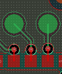
    TER: The CC3220MODSF SPI interface is routed directly to test points (3 -4 mm routing) and are not connected to anything else on the PCB as shown below:

    - The SPI lines must not be driven by any other source while programming.

    TER: After programming the serial flash the buffers driving the SPI lines in the programming jig is set to high-z

    - The CC3220 is held in reset during programming to prevent I/O contention

    TER: As shown in the logic analyzer plots the reset is kept low until the programming is done. 

    Since the SPI lines are connected only to test points, what more do you expect to find in a review and are more guide lines for SPI programming listed in a different document? 

  • Hi,

    We would like a schematic review to ensure your design follows our guidelines with the reset circuit. 

    Thanks,
    Jacob

  • Please refer to which reset guide lines you are referring to. The only thing I have been able to find is that the RESET_N line should be connected to the host MCU and if the state of the reset pin is not defined for all operating conditions the VBAT_RESET line should be connected to VDD to use an internal 100 kohm pull-up. 

    In our case we use the VBAT_RESET line connected to VDD. At the time of first time boot, which is the issue here, the RESET_N line is controlled by the programming jig. How the reset line is behaving is shown in the logic analyzer plots. Could you share your thought process why the external reset circuitry could impact the issue we are seeing since the reset line is actively controlled? 

  • Hi,

    My thought process with the reset circuitry is that the CC3220 is held in reset while programming over SPI. I'm adding a team member who can be more of assistance here.

    BR,

    Jacob

  • Hello Ghost,

    What does TER stand for?

    You mentioned this occurs a certain percentage of the time and there are no problems other times, so it sounds like a hardware issue.

    As for the reset circuit, I wanted to check to see if you had any components tied to the reset external to the module as some customers mistakenly do. 

    It would help if you could request a schematic and layout design review so that we could first ensure that your design is optimal and follows our guidelines before debugging this issue any further.

    BR,

    Seong

  • I have to see what I'm willing to send off for a review since it's a lot on the schematic and layout that is not relevant to the WiFi.

    Could you elaborate on 

    "As for the reset circuit, I wanted to check to see if you had any components tied to the reset external to the module as some customers mistakenly do. "

    I can't find any recommendation on the reset network in the documentation, please refer to the recommendation and give examples on mistakes. Also, as pointed out before, the reset line is actively driven by the test jig ("host MCU" in this case). As long as the logic analyzer plota show that the reset line is logic low/ high, how can other components on the reset line impact the result? 

    "What does TER stand for?": Some companies use 3 letter abbreviation of employee  names, this has been mine since mid '90 and that was what I used on E2E before.   

  • Ghost,

    That's right; I remember seeing your name on E2E.

    There is a 100k pull up and 10nF tied to the CC3220 IC's reset pin internal to the module (see image below). 

    Some customers add resistors and/or capacitors to the reset circuit external to the module which can impact the rise/fall time of the reset signal.

    BR,

    Seong

  • - The design has no passives connected to the reset line. 

    - Under normal operation the WiFi module can be reset from 2 different sources. For first time boot the reset line is controlled by the programming jig and the other reset sources are in high-z.

     In https://www.ti.com/lit/ds/symlink/cc3220mod.pdf I can't find any limitations on rise/ fall time on the reset line. The size of the cap in the RC network connected to the reset line is not documented, the only place I could find anything about the RC network is here:

    "10.2.2 Reset The module features an internal RC circuit to reset the device during power ON. The nRESET pin must be held below 0.6 V for at least 5 ms for the device to successfully reset."

    Btw:

    "8.14.3 Device Reset When a device restart is required, the user may issue a negative pulse to the nRESET pin. The user must ensure the reset is properly applied: A negative reset pulse (on pin 35) of at least 200-mS duration."

    Any reason why reset low time is different in 10.2.2 and 8.14.3?

    --

    The RC component sizes are important at power-up to ensure that the reset is held low while power is ramping. But I can't see anything regarding this network in this case, where the reset line is actively driven while the power is stable.  

    As you see from the first plots in the original post, the WiFi module starts the boot-up (it starts reading from the external flash) in all cases. It's still unclear from the above why it randomly should stop the boot sequence due to the size of the components on the reset line. I would like a theory from TIs side on why the module behaves like it does.  

  • Ghost,

    The discrepancy in these two sections of the datasheet must be updated. The proper start-up of the module should be nRESET ramping up 1ms after VBAT is high. 

    If external passives are not connected to the reset line and if you can verify that the layout follows our guidelines, perhaps it is not a hardware issue. But it would be worth double checking the design so please request a review after you've determined what you are able to share with us.

    BR,

    Seong

  • A couple of HW questions:

    From the datasheet:

    "Depending upon routing resistors and battery type, TI recommends adding two 100-µF ceramic capacitors"

    I note that we use less than the recommended here. But the issue I'm seeing comes when the board is mains powered. Do TI have more details on how large cap that has to be used for a given power source and routing resistance? 

    "Do not run signal traces underneath the module on a layer where the module is mounted."

    I see that we have for some reason done this with pin 18 (4.4 mm), 21 (3.9 mm), 23 (3.3 mm), 24 (5.7 mm ) , 35 (2.5 mm), 42 (11.2 mm).  Has TI any experience with what could happen if some signals are routed on the same layer or is this a generic recommendation? 

  • Ghost,

    When your board is mains powered vs. battery, is the CC3220MODSF powered from a different regulator?

    Depending on the VBAT voltage level, the peak calibration current can be as high as 620mA. Calibration is done when the device first boots up. See Section 8.5 in the datasheet. What is the max current output of the voltage regulator on your board supplying the CC3220MODSF?

    The bigger the ceramic capacitor, the more stable it is with DC voltage. Ensure that you use a cap with voltage rating that is 10V or higher. Are you observing significant voltage drops on the power rail when the module is resetting? 

    The guidance to not run signal traces underneath the module is to ensure there is a solid GND plane under the module for stable system optimal thermal dissipation as the datasheet states. So if the GND plane underneath is not solid, the module could be overheating. Though I am not certain as to how much, but high temperatures could also affect the conductivity of the signal traces.

    BR,

    Seong

  • Measuring the VDD supplying the WiFi module the power rail looks ok when the WiFi module boots but the regulator that supplies the module looks like it's not dimensioned for the calibration current draw. The designer of this board is out this week so I have to discuss with him next week on why and what considerations have gone into calibration and calibration settings (as far as I understand it it can also run at other times than first time boot) 

    As far as I could see from the datasheet the calibration is done at one point during the 1.3 s bootup. Do you know more exactly when this is run (at the start, mid, end...) in the start-up sequence? 

  • Ghost,

    There is more information about the device's calibraiton modes in Section 4.9 of the CC3220 Network Processor UG here.

    If you are referring to Table 8-2 in the datasheet, are you asking exactly when the calibration occurs during the 1.35s T3 window? 

    BR,

    Seong

  • If you are referring to Table 8-2 in the datasheet, are you asking exactly when the calibration occurs during the 1.35s T3 window? 

    Yes

  • Ghost,

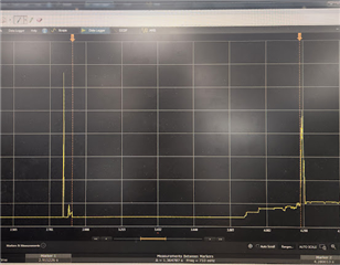
    I measured the current draw when powering up the device. The small waveform that follows after the initial inrush current is 24ms long so this must be the Hardware Wake-up period. 

    I measured the time from right after this small waveform to the next spike (pictured above) which is the calibration and it was ~1.35s. So the calibration must occur at the end 

    BR,

    Seong

  • Thank you, I will look closer into this next week when more people is back from vacation. 

  • Ghost,

    Sure thing. Keep us posted. 

    Thanks,

    Seong

  • We use 22 uF on the 3.3 V net to the module (more decoupling cap is placed on the other side of the bead). Based on the suggested cap size this is on the low end but when I measure I only see a few mV of ripple after ~1.3 s after the reset is pulled high. Also, if you look at the plots in the first post, I see a difference between working and not working runs after about 1.1 s after reset is pulled high which should rule out the calibration current as the problem. 

  • Ghost,

    You mentioned that this is not a problem when your board is battery-powered.

    What is the difference in hardware when the board is mains vs. battery-powered?

    BR,

    Seong

  • You mentioned that this is not a problem when your board is battery-powered.

    Where have I written that it works when it's battery powered? The first time boot is always done in production test and that is always done mains powered. 

  • Ghost,

    I made this assumption from when you said, " But the issue I'm seeing comes when the board is mains powered".

    Have you tried this on a CC3220MOD LaunchPad?

    BR,

    Seong

  • I believe some tests have been done with the Launchpad before my time but I'm not sure how the serial flash was programmed in this case. 

    I'm working with a production test jig and it would require more time than I have at the moment to try to adapt the jig to program the Launchpad and not our board. The HW has to be changed but I assume that also a new FW image for the serial flash has to be made based on usage of different DIOs etc of the module. 

    As I read this thread, TI has no theories on why I need 3 resets with a given timing to get it to work? The last reset I use should also be independent of HW solutions, is it documented somewhere that a reset after first boot could be required?  

  • Hey TheGhostOf,

    Apologies for the delay, I will try to run the test this week. 

    BR,
    Jacob

  • Did you manage to test some?

    Have you ever checked why this module (and chip) does not have an errata? The ARM core alone have known bugs and a complex chip like this has to have something that should have been covered by an errata. 

  • Hi,

    I discussed missing errata for CC32xx with TI few times. But I never got satisfied answer. But I think why "real" real public does not exist it complexity of SoC itself. Because errata will need to cover all changes at NWP and MAC firmware. And this seems me not realistic...

    Just a one idea. Are you sure that you are not accidentally powering module via some other pins? Let say you have disconnected Ucc but some other pins stay connected (e.g. UART RX). This can partially power module via ESD protection diodes at pins. This can cause stuck at bootlaoder.

    Jan

  • Errata: Could be the case since I could not find an errata for a similar non-TI module.

    Boot: All SoP pins are low when booting. In this mode I get the understanding that the device should be fairly insensitive for undefined state on other pins? Also, why should it stop booting after the SPI but has been active in 2.5 ms as the figures show in the first post? 

  • Hi,

    As to be honest, I was not be able convinced TI that even smaller things like proper documenting changes of NWP make sense.

    Do you have connected other pins at moment when Ucc is not connected? It this pins are at high state (e.g. pull-up or Hi-Z) it may to partially power MCU, and it can cause very, very weird behavious. This is similar as any other low power MCU at market. There is no relation with SOP mode. This is common "feature" of almost all low-power silicon devices. But if you don't have such connection,  that this is not reason of your issue.

    Jan