This thread has been locked.

If you have a related question, please click the "Ask a related question" button in the top right corner. The newly created question will be automatically linked to this question.

WL1807MOD: How to connect to WL1807 using RTTT?

Part Number: WL1807MOD
Other Parts Discussed in Thread: TXS0108E, TXB0104,

Hi team,

Here's the request from the customer:

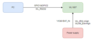
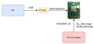
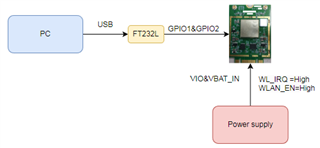
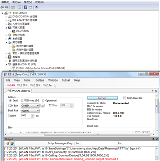
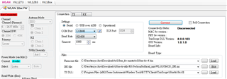
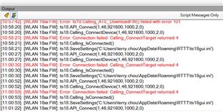
Refer to the following figure in the guide and the status cannot be activated.

GIPO1&GPIO2 to PC COM port

VCC =3.3V

WLAN_EN=High

Are the settings correct?

Could you help check this case?

Thanks and Regards,

Nick

  • Hi Nick,

    I need some more information about the setup. How has the customer connected the WL1807 to the PC? Are they using a UART to USB adapter? Are they using a TI evaluation board? if so which one?

    This error is normally because the hardware interface is incorrect, like the correct signals aren't connected.

    Regards,

    Jonathan  

  • Hi Jonathan,

    Here's customer's further reply:

    How can use detail RTTT tool setting to WL1807 wifi card?

    Thanks and Regards,

    Nick

  • Hi Nick & Jonathan,

    The picture setting WL1807 connect to PC.

    I have no use TI EVB.

    Thanks and Regards,

    Terry

  • Hello Terry,

    Do you see the device come up in your PC's device manager? If so is the COM port you choose in RTTT match?

    Also, how have you pulled up the WL_IRQ line? The hardware user's guide https://www.ti.com/lit/ug/swru437b/swru437b.pdf?ts=1679901936858 for the WL18xx says to use a 10k pull-up (to 1.8V).

    Also, please verify that the device is in debug mode by verifying the following lines: UART_DBG_BT = 1, AUD_OUT_BT = 0.

    Regards,

    Jonathan 

  • Hi Nick & Jonathan,

    UART_DBG_BT = 1, AUD_OUT_BT = 0.

    I use WL1807  is only WIFI ?  

    WL_IRQ pin add 10K and wire to TXS0108E pin number 10.

    Thanks and Regards,

    Terry

  • Hi Terry,

    Yes you are right, those pins are not connected in the WL1807, so no need to verify them.

    Do you see the WL1807 in the device manager on your PC?

    Regards,

    Jonathan  

  • Hi Nick & Jonathan,

    no

    [10:18:06] [WLAN 18xx FW]: Error: ts18.Calling_ATE_DownloadFW() failed with error 101
    [10:18:07] [WLAN 18xx FW]: ts18.LoadTsDll("C:\\Program Files (x86)\\Texas Instruments\\Wireless Tools\\RTTT\\Clients\\TrioScope\\18xx\\ts18x.dll")
    [10:18:07] [WLAN 18xx FW]: ts18.Calling_GetDllVersion("C:\\Program Files (x86)\\Texas Instruments\\Wireless Tools\\RTTT\\Clients\\TrioScope\\18xx\\ts18x.dll")
    [10:18:10] [WLAN 18xx FW]: ts18.API_Connect(1,46,921600,1000,2,0)
    [10:18:10] [WLAN 18xx FW]: ts18.Calling_ConnectDevice(1,46,921600,1000,2,0)
    [10:18:12] [WLAN 18xx FW]: Error: Connection failed: Calling_ConnectTarget returned 4
    [10:18:12] [WLAN 18xx FW]: ts18.Calling_IsConnected()
    [10:18:12] [WLAN 18xx FW]: ts18.SaveSettings('C:\Users\terry.chou\AppData\Roaming\RTTT\ts18gui.ini')
    [10:18:14] [WLAN 18xx FW]: ts18.API_Connect(1,46,921600,1000,2,0)
    [10:18:14] [WLAN 18xx FW]: ts18.Calling_ConnectDevice(1,46,921600,1000,2,0)
    [10:18:16] [WLAN 18xx FW]: Error: Connection failed: Calling_ConnectTarget returned 4
    [10:18:16] [WLAN 18xx FW]: ts18.Calling_IsConnected()
    [10:18:16] [WLAN 18xx FW]: ts18.SaveSettings('C:\Users\terry.chou\AppData\Roaming\RTTT\ts18gui.ini')

  • Hi Terry,

    If the WL18xx is not coming up in your PC's device manager then the RTTT will not be able to connect. That is the origin of the error you are seeing: Error: Connection failed: Calling_ConnectTarget returned 4.

    This means your issue is likely hardware related, the interface between the WL1807 and your PC is incorrect. 

    Can you share a schematic of the WL1807 and it's connection to the PC. Including the level shifters and supply.

    Regards,

    Jonathan  

  • Hello  Jonathan,

    The attached file is my schematic and setting block diagram  RTTT tool.

    FDG4560_V091.pdf

    Regards,

    Terry

  • Hi Terry,

    If you see no changes in your device manager on your PC when you disconnect and connect the USB then the issue is with the hardware connections. I have a few questions after going through your schematic:

    1. Did you connect the FT232L to the GPIO1 and GPIO2 lines (called WL_TX and WL_RX in your design) at 3.3V voltage or 1.8V? FTDI protocol normally can sense 3.3V only so make sure you connect those lines after the TXB voltage translator. 

    2. It looks like your WL_EN pin is pulled down to ground with resistor R2, this signal should be high.

    3. You should check to see if the driver for this FTDI cable you are using is installed on your PC, however if this was the case you will still see a new com port come up in the device manager, it would just not know that is is FTDI without the driver. 

    You should consider trying to connect the relevant lines to an oscilloscope or logic analyzer to see if the signals are actually transmitting data at the anticipated voltage level.

    Keep me updated on your progress.

    Regards,

    Jonathan 

  • Dear Jonathan ,

    1.WL_TX and WL_RX two Line from TXB0104 pin 10,11 to my PC..

    2..No Load R2

    3.same com port 

    Regards,

    Terry

  • Hi Terry,

    So I see the device does show up in the device manager of your PC, I thought it didn't. I think you should check the WL_TX and WL_RX lines in an oscilloscope to see if any data is being sent.

    Also try to pull up pin BT_UART_DBG (pin 43) and pull down BT_AUD_OUT (pin 57). Even though this device is not bluetooth enabled, these pins still need to be in that configuration for debug mode.

    WL_IRQ =1

    BT_UART_DBG =1

    BT_AUD_OUT =0

    Regards,

    Jonathan 

  • Hi Terry, 

    Any updates on this issue?

    Regards,

    Jonathan

  • Hello Jonathan

    sorry!!

    I testing WL1807 throughput on my board in two days.but

    I will use your method in next week.

    WL_IRQ =1

    BT_UART_DBG =1

    BT_AUD_OUT =0

    Regards,

    Terry

  • Hello Jonathan

    I use iperf3 to test throughput Meanwhile WL1807 have a new issue.
    This is low frequency noise my ear under shield case.
    The attachment file is my module setting. 
    BR,
    Terry

  • Hi Terry,

    Can you give more clarification of what the issue is? 

    As I understood you hear some low frequency buzzing? Or you are picking up some low frequency noise some other way? How are you measuring under the shield case of the module?

    Can you provide some information on when this is happening? At what modulation and rate are you testing?  

    Regards,

    Jonathan 

  • Hello Jonathan 

    The attachment file is testing environment.

    I try independent power 3.3v and 1.8v to Wl1807.

    WL1807MOD still have sound.

    Image 7.zip

  • Hi Terry,

    Thanks for the clarification here. This is very unusual that you are hearing noise from the WL1807. You should try to lower the power output of the TX by changing parameters in the INI file (refer to this guide https://www.ti.com/lit/an/swru422a/swru422a.pdf ). You can try to see if lowering the output power will decrease or eliminate the noise. 

    You should also try to measure the current draw of the WL1807, if you have a way to do so on your board. Measure the current drawn by only the WL1807mod itself, without all of the other components on your board.

    Let me know what results you find, but these tests you are running indicate that something may be faulty in the WL1807mod you are using. Even at max power the WL1807 should not be buzzing.

    Regards, 

    Jonathan