This thread has been locked.

If you have a related question, please click the "Ask a related question" button in the top right corner. The newly created question will be automatically linked to this question.

CC3220MODA: Error when trying to flash SLI image

Part Number: CC3220MODA
Other Parts Discussed in Thread: SYSCONFIG, UNIFLASH

Hello support team.

I recently returned to work on the CC3220 project and found a problem when trying to load the SLI image.
Last time I did this I was using CCS version 10.xx.
I reinstalled the latest version of CCS, version 12.3.0.00005 on a new PC.
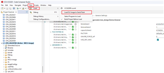
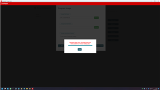
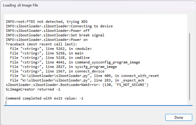
The project compiles correctly and generates the SLI file, however when I try to transfer the file using the "Load SLI Image to Serial Flash" option, the following message appears indicating an error.
Please could you tell me what is going on.

Thank you Carlos Takahashi.

---------------------------------------------------------------------------------------------------------------------------------------------------------------------------------------------------------------------------------------------------------------------------------------

Invoking command: C:\ti\simplelink_cc32xx_sdk_6_10_00_05\source\ti\drivers\net\imagecreator\bin\SLImageCreator.exe syscfg program --file D:\NCB\CCS-CC3220\CPU_20220708\MCU+Image\syscfg\CPU_20220708.sli --json D:\NCB\CCS-CC3220\CPU_20220708\MCU+Image\syscfg\ti_drivers_net_wifi_config.json

INFO:root:FTDI not detected, trying XDS
INFO:slbootloader.slbootloader:Connecting to device
INFO:slbootloader.slbootloader:Power off
INFO:slbootloader.slbootloader:Set break signal
INFO:slbootloader.slbootloader:Power on
INFO:slbootloader.slbootloader:Clear break signal
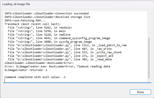
INFO:slbootloader.slbootloader:Connection succeeded
INFO:slbootloader.slbootloader:Received storage list
INFO:root:Patching RAM...
Traceback (most recent call last):
File "<string>", line 5262, in <module>
File "<string>", line 5258, in main
File "<string>", line 5228, in cmdline
File "<string>", line 4641, in command_sysconfig_program_image
File "<string>", line 2880, in syscfg_program_image
File "W:\slbootloader\slbootloader.py", line 1312, in _load_patch_to_ram
File "W:\slbootloader\slbootloader.py", line 607, in _raw_write
File "W:\slbootloader\slbootloader.py", line 533, in _write_raw_chunk
File "W:\slbootloader\slbootloader.py", line 271, in _expect_ack
File "W:\slbootloader\slbootloader.py", line 302, in _read_data
slbootloader.slbootloader.BootLoaderError:
Error: SLImageCreator.exe: BootLoaderError, Timeout reading data
SLImageCreator returned -1

Command completed with exit value: -1

  • Are you trying to flash the device (where is the "Load SLI Image to Serial Flash" option?)?

    Have you tried this with uniflash?

  • Hello Kobi.
    The "Load SLI Image to Serial Flash" option is in the CCS, in the Run -> Load -> Load SLI Image to Serial Flash menu, as shown in figure 1.
    I also tried it with UniFlash and the result can be seen in figure 2.

    figure 1.

    figure 2.

  • Have you changed anything inside the image.syscfg?

    Did you try to press the Flash button (rather than expand it and using the "Load SLI...")?

    In uniflash, I saw a similar issue that was fixed when i retried, but you may have an issue with the SLI image.

    I'll also try to check with our tools team but this is very basic use case that should just work.

  • Hello Kobi.

    I managed to borrow an XDS110 probe and a CC3220 launchpad.
    In figure 1 I used the XDS110 probe with the X1 tag, I was able to correctly flash the image to the target T1, as shown in figure 2.
    In figure 3, I changed the flat cables and the usb cable from the X1 probe to the X2 probe, without any change in the T1 target, but the procedure fails as shown in figure 4.
    In figure 5, I used a CC3220 launchpad, marked L1, connected to target T2, but the same error occurs as shown in figure 6.
    In all attempts, the images were generated in development mode. I did the rebuild of the project every time, to make sure that the communication with the target was happening correctly.
    In figure 7 using the xdsdfu program I checked the firmware version of the tools.
    Figure 8 shows the X1 and X2 identification labels.
    I need to find out what's different about X2 and L1 that makes the image write fail.

    Thank you.

    figure 1.

    figure 2.

    figure 3.

    figure 4.

    figure 5.

    figure 6.

    figure 7.

    figure 8.

  • Hello Carlos Takahashi,

    Did you try updating the firmware on the XDS110 Debugger Probe X2. 

    Its hard to tell from the picture but could you make sure the Launchpad has all the jumpers that lead from the top of the board to the IC are not populated? Could you upload a clearer picture of the setup when using the Launchpad?

    BR,

    Jessica

  • Hello Jessica.

    In figure 7 of the previous post, using the xdsdfu program, it is possible to see that the two XDS110 probes and the Launchpad have firmware version 3.0.0.25.

    Can the firmware version of probes and launchpad be checked with the xdsdfu program?

    Which firmware update version should be installed?

    Before talking about the launchpad, why does one of the XDS110 probes work and the other doesn't?

    As I said I just changed the flat cables and the USB cable, however the other probe didn't work.

    Regarding Launchpad, I am uploading a new picture, describing the binding of the signals:

    Reset in violet color;
    TX in yellow color;
    RX in green color;
    GND in blue color.

    The signal jumpers were removed on the Launchpad and connected to the left pin, as shown in the image.

    The other cable indicated as JTAG CONNECTOR is equivalent to the XDS110 OUT connector.

    Thank you.

  • Hello Jessica.

    I forgot to mention:
    Through that connection scheme I showed in the previous post, I can compile and generate the image in development mode.
    To create the image in development mode, it is necessary for the probe to communicate with the target to obtain the MAC address and generate a personalized and unique image.
    So I guess the wiring diagram must be right.


    Thank you very much.