- Ask a related questionWhat is a related question?A related question is a question created from another question. When the related question is created, it will be automatically linked to the original question.
This thread has been locked.
If you have a related question, please click the "Ask a related question" button in the top right corner. The newly created question will be automatically linked to this question.
Tool/software:
Hi TI supervisor,
My company product(mass production already) used CC3235MODASF module.
Our product has sold region is Taiwan, if this module had NCC ID it's useful for reduce our product certification test cases and loading.
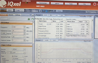
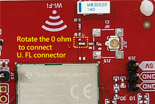
The cable loss is normal which used for connected DUT and instrument(IQ xel)
Could you explain what you mean with "normal cable loss". When connecting to the Tester it is important to take into account the attenuation of the cable, since that will affect the measured TX power.
If you wish to test conducted it may be best to do it closer to the RF pin on the module. Th
C:\ti\CC3xxx_RadioTool_1.0.3.19\Source Files\Source Projects\radiotool_CC3235SF_LAUNCHXL_tirtos_ccs\MCU+ImagePlease help to confirm is the burned image correct?
That seems to be the correct image, but let me verify and get back to you.
The CC3235MODASF has not been certified for NCC, you can downlead the test reports for the CE certification at https://www.ti.com/tool/SIMPLELINK-CC3XXX-CERTIFICATION.
Hi Jessica,
Very Glad to get your reply.
There was use network Analyzer to get the IL and RL of cable, the cable loss result is under 2 db.
According to the specification, the actual test results should not be so low in the 5.0GHz bands. (But in 2.4G bands is around 14 dBm, it's normal))
(15 - 2 = 13, but actually result is 7dBm)

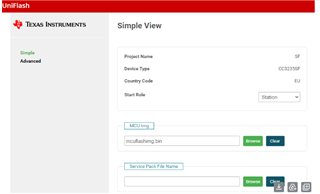
Hi Jessica,
It's been 7 days passed. Do you have feedback if Eric is using the right image for 11a band test?
Greetings,
Apologies been out of office last week. Yes the image used to flash the device is correct
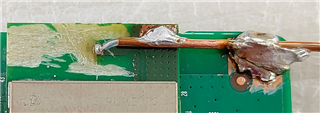
To minimize reflections (and consequently poor signal) the soldered coaxial cable should be closer to the RF output path, and not to the copper of the Antenna design on the PCB (refer to image below).
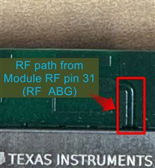
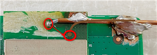
Part of the issue might be that the cable added for doing the conducting testing is on the copper of the PCB antenna design, instead of only the RF path. (refer to image below). Also the copper path carrying an RF signal should never have any sharp turns which still applies when soldering on a cable, as such attempt solder a new cable with results similar to the drawing on the image below.
BR,
Jessica
Hi Jessica,
Thanks for your feedback.
We will try to reconnnet the RF feed point as your mention ASAP.
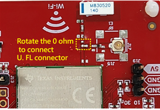
As described for the first time on E2E(7/26), there was also did conducted mode test on EVB in parallel.
The EVB test result was the same with PCBA status.(in 2.4GHz bands is around 14 dBm, but only 7 dBm in 5.0GHz band)
Do you have any idea about EVB test result?
Thanks.
Hi Jessica,
Change the measurement point according to your suggestion, and the test result is still only 7 dBm(the same with before rework) in 5.0GHz bands.
Do you have any other suggestions to the issue?
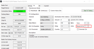
By the way, when using radio tool to operate power level in 5.0GHz band cannot be selected (as below screeshot,but 2.4GHz band can be select) Is this normal?
Thanks for your kindly help.


Hi Eric,
That is interesting, could you confirm what specific transmission parameters were used to have 7dBm loss, or is it for all 5Ghz channels? When measuring the resulting TX power what settings are being used in the tester?
Hi Jessica,
Following screenshot was radio tool setting for yor reference. if there had problem, please help to tell us.
And the tester is IQ Xel, following screenshot is setting screenshoot for yor reference.
Most of all, the 5.0GHz Tx conducted power level of EVB is the same with PCBA rework(remove the antenna pattern) by hand.
Please kindly give us help to this issue.
Thanks.
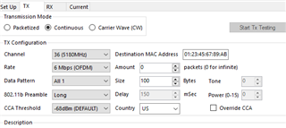
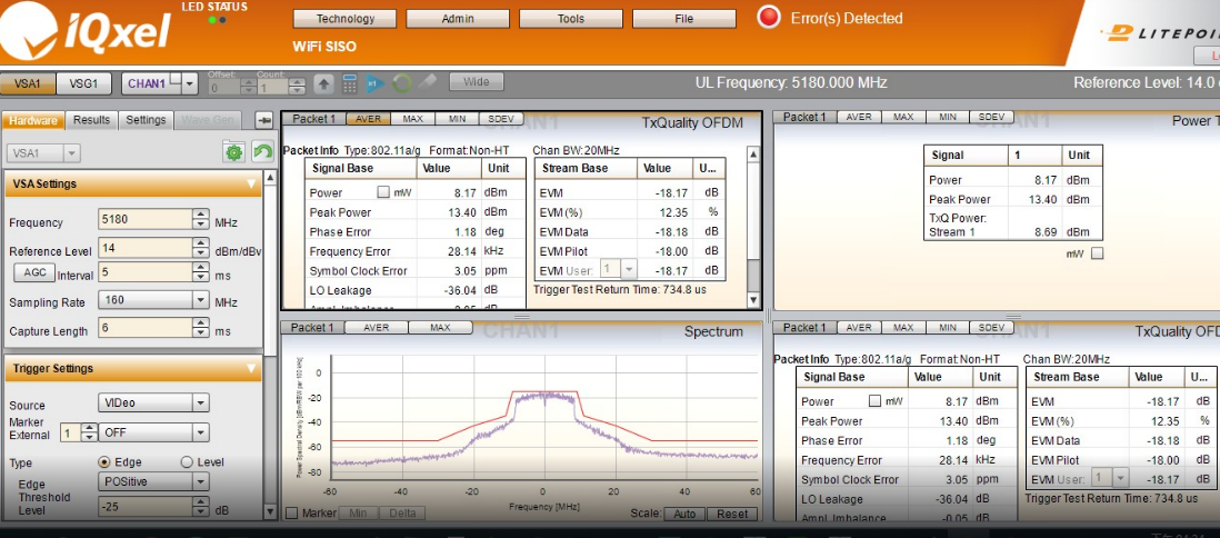
Hi Jessica,
Please kindly help to confirm whether the data of power level in the following table is reasonable.
Thanks.
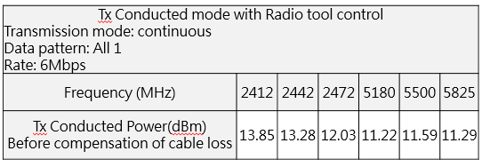
Hi Jessica,
Plaese ignor previous e-mail.
Revise the test data as following table.
Please kindly help to confirm again whether the data of power level in the following table is reasonable.
Thanks.
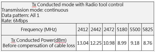
Hi Jessica,
Please ignore the last email and refer to this.
Please kindly help to confirm again whether the data of power level in the following table is reasonable.
Thanks.

Hi Jessica,
Please kindly help to confirm whether the data of power level in the following table is reasonable.
Thanks.

Hi Jessica,
Please kindly help to confirm whether the data of power level in the following table is reasonable.
Thanks.

Hi Jessica,
Sorry to bother you again, there is no reply form you for 13 days.
Please kindly help to confirm whether the data of power level in the following table is reasonable.
Thanks.

Hi Eric,
According to your latest Tx conducted Power measurement table it seems that these power levels are aligned with FCC limitations with some minor deviation form our targets on FCC (<= 0.5dB).
Question, what was changed from the measurement showing ~9dBm at 5GHz channels to the latest which shows ~11.5dBm ?
Regards,
Guy
Hi Mr. Bashan,
Thanks for your reply.
First, the reply of your question is that We try to rework "another PCBA" and make sure connected point of copper cable as close to the module(CC3235MODAS) as possible we can.
The targer power was higher than old one around 2db.
But I have a question as mention in previous mail.
The EVB(CC3235MODSF) test results were around 8.5~9.5dBm at hi/mid/lo channels in 5.0GHz band.
Do you have any comment of EVB test result?
Gretings Eric,
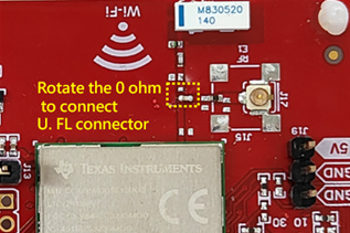
I can only assume that the power loss on the EVB may be caused by a damaged UF.L connection (component J17), or the EVM used is damaged. Have you been able to test the power with another EVB?
Could you confirm that the CC3235MODASF soldered on to your PCB board now transmits the expected conducted power?
Also apologies for the delay, I have been out of office till now.
BR,
Jessica