Tool/software:
Champs,
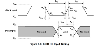
In the process of design validation customer is inspecting the interface signals. One concern pertains to the setup timing for the input data signal before the rising edge of the CLK. The image below shows the CLK (Yellow) and D3 Data signal on the WIFI (Blue):

The table below is the other data signals compared to the expected measurements from the datasheet:
|
Parameter |
Expected |
Measured D0 |
Measured D1 |
Measured D2 |
Measured D3 |
|
Clock frequency, CLK |
<52MHz |
48.04MHz |
48.01MHz |
47.96MHz |
47.93MHz |
|
High Period |
>7ns |
8.48ns |
8.56ns |
8.32ns |
8.56ns |
|
Low Period |
>7ns |
8.32ns |
8.36ns |
8.48ns |
8.4ns |
|
Rise time, CLK |
<3ns |
2.16ns |
2.12ns |
2.12ns |
2.04ns |
|
Fall time, CLK |
<3ns |
1.96ns |
1.8ns |
1.76ns |
1.84ns |
|
Setup time, input valid before CLK ↑ |
>6ns |
3.2ns |
3.28ns |
3.72ns |
3.08ns |
|
Hold time, input valid after CLK ↑ |
>2ns |
3.44ns |
3.48ns |
3.4ns |
3.48ns |
From the capture it seems to be hard to achieve the >6ns setup time spec, is there any screen captures or testing data that customer can use for reference?
The data signal also shows some asymmetry, is that also expected ? If this looks off to you as well we would appreciate your comments as to what could cause this and how this can be improved
thank you
Michael