LAUNCHXL-CC3235SF: CCS download with MCU+Image

Part Number: LAUNCHXL-CC3235SF
Other Parts Discussed in Thread: CC3235SF, UNIFLASH, SYSCONFIG, CC3551E

Tool/software:

Champs:

  #1. I can perform standalone testing for verifying the JTAG on the CC3235SF LP EVM.

  #2. After building the code, the CCS gives me the below error.

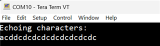
Cortex_M4_0: GEL Output:
Memory Map Initialization Complete
CS_DAP: Error connecting to the target: (Error -1170 @ 0x0) Unable to access the DAP. Reset the device, and retry the operation.

If error persists, confirm configuration, power-cycle the board, and/or try more reliable JTAG settings (e.g. lower TCLK). (Emulation package 20.0.0.3178)

How to fix this?

BR Rio

  • Hi Rio,

    It is likely that device is not at development mode. You can use Uniflash or Sysconfig image creator and switch device into development mode. At production mode is JTAG locked from security reason.

    Jan

  • Hi Jan:

      Thanks.

       I simply introduce myself.

       I well-know the CC / WL family for years. (but no include the CC323x family, after 2026, I main focus on TI Processor  + MCU.

       IE: CC323x family is the lack one in my career.

       Now, I have many questions:

              #1. In my CCS / Image.sysconfig, I'm sure I config as "Developing" mode.

                    And I rebuild it as "MCU+IMAGE". (Clean build).

                    After this, I cannot success flash my EVM thru CCS. (Debug or Download icon.)

                   Those 2 steps will give me the above error.

              #2. I can flash success with Uniflash, but, it seems the code ins not flashed actually. (Stanger.)

              #3. The uniflash is flashing thru Main UART? (Application UART)?

        My I have your email? Thus I can have a online debug with you?

        Maybe 10mins is enough.   .

    BR Rio

  • Hi JD:

       #1. The Download is okay now, Not sure why the developing mode is not working on my CCS, I re-try again, issue is gone.

       #2. I used this example : UART echo, and change the pinmux as the following.

             Q1. Why the Application console didnot dump anything.?

             Q2. I wire those 2 pins (as the below pic.), TX connected to RX, .

                    It should have some words on my teraterm, right?


    BR Rio

    BR Rio

  • Hi Rio,

    I think it does not make much sense build new project at CC32xx, due to hardware limitations (Eg. TLS 1.0 for EAP security). I think for new development is better to use new CC3551E.

    1) How to use SysConfig ImageCreator you can find at SimpleLink academy at TI resource explorer.

    2) I am not sure why Uniflash not working for you. At TI resource explorer you can find how to use Uniflash software.

    3) CC32xx devices uses two ways programming. JTAG can be used for programming from IDE for a development purpose only (uploading code into internal XIP flash or RAM for S devices). Content of SPI flash (called sFlash) is programmed via UART and ROM bootlaoder. At production line guide you can find more detail about UART connection.

    I am sorry, but I don't have enough time provide support via email. This can do guys from WiFi App team. As to be honest, I don't use CC32xx for more than two years, now I am working at project with STM32H7 (TI does not have similar MCU at product portfolio).

    Sorry, I never used this example. Please wait for answer from WiFi team or you can write message directly to Shlomi Itzhak.

    Jan

  • Hi JD:

    Thanks.

    Hi Shlome:

       #1. By using the Original sysconfig, the console gives me this UART echo.

       #2. Now, How to / which TX / RX pin I can use for testing with other EVM for proving UART is Sending / Receiving thru the EVM TX/RX pins?

             What are the free pins I can use for UART TX/RX?

    BR Rio


  • Hi Shlomi:

       #1. I have modified the UART0 as the P03 / P45 pin to be the TX/RX.

       #2. But I cannot measure any single from those 2 pins.

       #3. Meanwhile, I connect those 2 pins together, the Console has no Echo the Char I input.

    Any comments?

    BR Rio


  • Hi,

    You cannot use pin P45_GPIO_31 at CC3235SF devices.This pin is used for internal DC-DC for powering XIP flash. Please see datasheet for CC3235SF or CC3235SF LP schematic.

    Jan

  • Hi,

    I added UARTp07 and p08 and changed the code to open the 2nd UART I created.

    Then, I connected with an external level shifter to the new created UART and I get the typed characters.

    Shlomi

  • Hi Shlomi:

     May you share the Sysconfig + modified code to me?

     Sorry, my customer is waiting.

    Thanks.

    BR Rio

  • Hi Shlomi:

     #1. By setting as the same with you, I cannot measure any signal from the EVM.


      #2. Do I need to modify the code as the below?

    static const UART2CC32XX_HWAttrs uart2CC32XXHWAttrs0 = {
    .baseAddr = UART0_BASE,
    .intNum = INT_UART0,
    .intPriority = (~0),
    .flowControl = UART2_FLOWCTRL_NONE,
    .rxDmaChannel = UDMA_CH8_UARTA0_RX,
    .txDmaChannel = UDMA_CH9_UARTA0_TX,
    .rxPin = UART2CC32XX_PIN_45_UART0_RX,
    .txPin = UART2CC32XX_PIN_03_UART0_TX,
    .ctsPin = UART2CC32XX_PIN_UNASSIGNED,
    .rtsPin = UART2CC32XX_PIN_UNASSIGNED,
    .rxBufPtr = uart2RxRingBuffer0,
    .rxBufSize = sizeof(uart2RxRingBuffer0),
    .txBufPtr = uart2TxRingBuffer0,
    .txBufSize = sizeof(uart2TxRingBuffer0)

    BR Rio

  • Rio,

    First, I would leave the original UART that goes into PIN_55 and PIN_57 as is and just add a new instance of UART. So I will have two UARTs as below:

    Second, I would  change the code such that the new UART is initialized. In this case, I need to initialize CONFIG_UART2_1 so in the uart2echo.c I would change "uart = UART2_open(CONFIG_UART2_0, &uartParams);" into "uart = UART2_open(CONFIG_UART2_1, &uartParams);"

    Third, I will connect an external level shifter that connects to P07 and P08 on the header and type characters and receive an echo back.

    Shlomi

  • Hi Shlomi: 

       Some questions:

             Q0. Why we need the Leve shifter if I connect the P7 + P8 together?

             Q1. You are using MCU+Image or Debug version?

             Q2. I can see the UART initial waveform while loading the Debug version.

                   But MCU+IMage will show me nothing.

             Q3. BTW, when using the Terraterm, I did perform the input from the console, the Waveform will not show me anything by both type: (Debug + MCU/Image.)

    any thing wrong I did?

    BR Rio

  • Hi Shlomi:

      1. On the EVM the P07/P08 are the pins that I measured. (Nothing happened.)

      2. I connect the P07 to P08 directly, no echo in the console :(.

    BR Rio

  • I used an external level shifter since I didn't want to touch the on-board FTDI. You can do it with the on-board FTDI as well. I am not sure why you connect TX to RX externally. In the echo example, the loopback is in SW. See picture of my setup when I use the FTDI and connect it to P_07 and P_08. It gets to the echo example SW and gets looped back to the terminal.

  • Hi Shlomi:

        please let me know the FDTI pins you connect to 07 and 08, thanks.

    BR Rio

  • P07 / P08 are the labels on the EVM?

  • yes, P07 and P08 on the EVM.

    The pins are connected to P06 and P07 (which are 3 pins jumper each) to the pin that is closer to the FTDI.

    This way, the FTDI is connected to the new pins instead of P57 and P55.

    Shlomi

  • Hi Shlomi:

    The problem is resolved, thanks for your supporting.

    I will close this.

    BR Rio

  • Hi Shlomi:

    The problem is resolved, thanks for your supporting.

    I will close this.

    BR Rio