This thread has been locked.

If you have a related question, please click the "Ask a related question" button in the top right corner. The newly created question will be automatically linked to this question.

CC3351: [CC33xx SDIO] Driver init failed with "sdio read failed (-84)" on Linux 6.1.102

Part Number: CC3351

Tool/software:

Dear TI Support,

We are currently working to integrate the CC33xx SDIO Wi-Fi module running Linux kernel v6.1.102. The driver was successfully compiled and loaded, but the Wi-Fi module fails to initialize properly.

  1. Hardware was detected via SDIO:

[root@Augentix:/root]# ls -l /sys/bus/mmc/deviceslrwxrwxrwx    1 root     root     0 Jan  1 00:03 mmc1:0001 -> ../../../devices/platform/soc@80000000/818c0000.sdc1_p0/mmc_host/mmc1/mmc1:0001
  1. Both kernel modules were loaded:

[root@Augentix:/root]# lsmod
Module                  Size  Used by    Not tainted           
cc33xx_sdio         3889      0
cc33xx                  90836    1
  1. However, during initialization, we encountered the following errors:

mmc1: new SDIO card at address 0001
random: crng init done
overlayfs: upper fs does not support tmpfile.
overlayfs: upper fs does not support RENAME_WHITEOUT.
overlayfs: failed to set xattr on upper
overlayfs: upper fs does not support tmpfile.
overlayfs: upper fs does not support RENAME_WHITEOUT.
overlayfs: failed to set xattr on upper
cc33xx_sdio mmc1:0001:2: Using SDIO in-band IRQ
wlcore: cc33xx_probe :: Start
wlcore: Wireless Driver Version 1.7.0.208
wlcore: WLAN CC33xx platform device probe done
wlcore: Chip wakeup
wlcore: Set BLKsize to 128
cc33xx_sdio mmc1:0001:2: sdio read failed (-84)
wlcore: ERROR IO error during core status read
wlcore: ERROR Fatal error during driver init, cannot recover
[root@Augentix:/root]#
=== AUGENTIX SPL v0.0.10 ===
DDR = Generic DDR3, 1600 MT/s, DDR3, 128 MB
DRAM INIT PASS, ret: 0x00000640

[PLL INFO]
CPU     Fvco 1008000000
        port3(N/A      ):         -1
        port4(N/A      ):         -1
        port5(N/A      ):         -1
DRAM    Fvco 1596000000
        port3(N/A      ):         -1
        port4(AXI DRAMC):  399000000
        port5(N/A      ):         -1
Cascade Fvco 1350000000
        port3(N/A      ):         -1
        port4(25M      ):   25000000
        port5(27M      ):   27000000
EMAC    Fvco 1500000000
        port3(EMAC     ):  250000000
        port4(QSPI     ):  150000000
        port5(ISP, VP  ):  375000000
Sensor  Fvco  891000000
        port3(N/A      ):         -1
        port4(IS, DISP ):  445500000
        port5(SENIF    ):  297000000
VENC    Fvco 1000000000
        port3(SDC 0    ):  200000000
        port4(SDC 1    ):  200000000
        port5(ENC      ):  333333333
Audio   Fvco  460800000
        port3(PWM      ):   46080000
        port4(Audio in ):   61440000
        port5(Audio out):     256000
MIPI TX Fvco  600000000
        port4(MIPI TX  ):   25000000

[Start FM]
 Cascade(P5) PASS       Freq :   27000000
     CPU(FB) PASS       Freq :   24000000
    EMAC(P3) PASS       Freq :  250000000
  Sensor(P4) PASS       Freq :  445500000
    Venc(P5) PASS       Freq :  333325000
     DDR(P4) PASS       Freq :  399000000
   Audio(P4) PASS       Freq :   61450000
 MIPI_TX(P4) PASS       Freq :   25000000
NOR Quad lane, 3 byte mode
NOR:Load u-boot from part=0x00007900 to 0x00008000 size 0x00042a14
SEC Uboot...OK


U-Boot 2016.03-00007-g8f1214a8 (Jun 03 2025 - 14:49:41 +0800)

I2C:   ready
DRAM:  128 MiB
MMC:   Synopsys Mobile storage: 0
Using default environment

*** Warning - bad CRC, using default environment

In:    serial
Out:   serial
Err:   serial
Net:   eqos_eth

Saving Environment to SPI Flash...
Erasing SPI flash...Writing to SPI flash...done
device 0 offset 0x100000, size 0x600000
SF: 6291456 bytes @ 0x100000 Read: OK
## Executing script at 01000000
sha256,rsa2048:key3+ ## Loading kernel from FIT Image at 01000000 ...
   Using 'conf-1' configuration
   Verifying Hash Integrity ... OK
   Trying 'kernel-1' kernel subimage
   Verifying Hash Integrity ... sha256,rsa2048:key3+ OK
   XIP Kernel Image ... OK

Starting kernel ...

** 20 printk messages dropped **
CLK: clk add provider finish
OF: /soc@80000000/usbc@A0000000: #phy-cells = 1 found 0
SCSI subsystem initialized
run auge_spi_setup done
m25p80 spi0.0: found w25q256, expected m25p80
5 cmdlinepart partitions found on MTD device nor_flash
Creating 5 MTD partitions on "nor_flash":
0x000000000000-0x0000000f0000 : "boot"
0x0000000f0000-0x000000100000 : "bootenv"
0x000000100000-0x000000700000 : "linux"
0x000000700000-0x000001b00000 : "rootfs"
0x000001b00000-0x000002000000 : "usrdata"
Import GPIO_HIGH_AT_PROBE solution
clk: Not disabling unused clocks
platform regulatory.0: Direct firmware load for regulatory.db failed with error -2
dw_mmc SDC1P0: card claims to support voltages below defined range
Kernel memory protection not selected by kernel config.
random: crng init done
mount: mounting devpts on /dev/pts failed: No such device


overlayfs: upper fs does not support tmpfile.
overlayfs: upper fs does not support RENAME_WHITEOUT.
overlayfs: failed to set xattr on upper
overlayfs: upper fs does not support tmpfile.
overlayfs: upper fs does not support RENAME_WHITEOUT.
overlayfs: failed to set xattr on upper
Starting logging: OK
Starting mdev...
Current system mode: factory
Initializing random number generator... done.
cc33xx_sdio mmc1:0001:2: sdio read failed (-84)
wlcore: ERROR IO error during core status read
wlcore: ERROR Fatal error during driver init, cannot recover
ifdown: interface wlan0 not configured
cat: can't open '/sys/class/net/eth0/address': No such file or directory
sh: 02:00:00:00:00:00: unknown operand
Starting crond: OK

[root@Augentix:/root]#
[root@Augentix:/root]#
[root@Augentix:/root]#
[root@Augentix:/root]#
[root@Augentix:/root]#
[root@Augentix:/root]# lsmod
Module                  Size  Used by    Not tainted
cc33xx_sdio             3889  0
cc33xx                 90836  1
[root@Augentix:/root]#
[root@Augentix:/root]#
[root@Augentix:/root]#
[root@Augentix:/root]#
[root@Augentix:/root]# dmesg
0x000000000000-0x0000000f0000 : "boot"
0x0000000f0000-0x000000100000 : "bootenv"
0x000000100000-0x000000700000 : "linux"
0x000000700000-0x000001b00000 : "rootfs"
0x000001b00000-0x000002000000 : "usrdata"
dwc2 a0000000.usbc: DWC OTG Controller
dwc2 a0000000.usbc: new USB bus registered, assigned bus number 1
dwc2 a0000000.usbc: irq 25, io mem 0xa0000000
usb usb1: New USB device found, idVendor=1d6b, idProduct=0002, bcdDevice= 6.01
usb usb1: New USB device strings: Mfr=3, Product=2, SerialNumber=1
usb usb1: Product: DWC OTG Controller
usb usb1: Manufacturer: Linux 6.1.102 dwc2_hsotg
usb usb1: SerialNumber: a0000000.usbc
hub 1-0:1.0: USB hub found
hub 1-0:1.0: 1 port detected
augentix-i2c: probing 80070000.i2c, <0x80070000 0xff>, irq 26.
i2c_dev: i2c /dev entries driver
Augentix AON WDT driver probed.
device-mapper: ioctl: 4.47.0-ioctl (2022-07-28) initialised: dm-devel@redhat.com
dw_mmc SDC0: fifo-depth property not found, using value of FIFOTH register as default
dw_mmc SDC0: IDMAC supports 32-bit address mode.
dw_mmc SDC0: Using internal DMA controller.
dw_mmc SDC0: Version ID is 290a
dw_mmc SDC0: DW MMC controller at irq 28,32 bit host data width,256 deep fifo
Initializing XFRM netlink socket
NET: Registered PF_PACKET protocol family
NET: Registered PF_KEY protocol family
Import GPIO_HIGH_AT_PROBE solution
dw_mmc SDC1P0: fifo-depth property not found, using value of FIFOTH register as default
dw_mmc SDC1P0: IDMAC supports 32-bit address mode.
dw_mmc SDC1P0: Using internal DMA controller.
dw_mmc SDC1P0: Version ID is 290a
dw_mmc SDC1P0: DW MMC controller at irq 29,32 bit host data width,256 deep fifo
mmc_host mmc1: card is non-removable.
device-mapper: init: waiting for all devices to be available before creating mapped devices
mmc_host mmc0: Bus speed (slot 0) = 100000000Hz (slot req 400000Hz, actual 400000HZ div = 125)
mmc_host mmc1: Bus speed (slot 0) = 250000000Hz (slot req 400000Hz, actual 399361HZ div = 313)
device-mapper: verity: sha256 using implementation "sha256-asm"
device-mapper: ioctl: dm-0 (rootfs) is ready
clk: Not disabling unused clocks
ALSA device list:
  No soundcards found.
platform regulatory.0: Direct firmware load for regulatory.db failed with error -2
cfg80211: failed to load regulatory.db
dw_mmc SDC1P0: card claims to support voltages below defined range
VFS: Mounted root (squashfs filesystem) readonly on device 254:0.
mmc_host mmc1: Bus speed (slot 0) = 250000000Hz (slot req 25000000Hz, actual 25000000HZ div = 5)
devtmpfs: mounted
Freeing unused kernel image (initmem) memory: 116K
Kernel memory protection not selected by kernel config.
Run /sbin/init as init process
  with arguments:
    /sbin/init
  with environment:
    HOME=/
    TERM=linux
    ethaddr=02:00:00:00:00:00
mmc1: new SDIO card at address 0001
random: crng init done
overlayfs: upper fs does not support tmpfile.
overlayfs: upper fs does not support RENAME_WHITEOUT.
overlayfs: failed to set xattr on upper
overlayfs: upper fs does not support tmpfile.
overlayfs: upper fs does not support RENAME_WHITEOUT.
overlayfs: failed to set xattr on upper
cc33xx_sdio mmc1:0001:2: Using SDIO in-band IRQ
wlcore: cc33xx_probe :: Start
wlcore: Wireless Driver Version 1.7.0.208
wlcore: WLAN CC33xx platform device probe done
wlcore: Chip wakeup
wlcore: Set BLKsize to 128
cc33xx_sdio mmc1:0001:2: sdio read failed (-84)
wlcore: ERROR IO error during core status read
wlcore: ERROR Fatal error during driver init, cannot recover
[root@Augentix:/root]#
/dts-v1/;
#include "hc1725-fpu.dtsi"

/ {
	model = "Augentix AGT725-11";

	soc@80000000 {
		i2c0: i2c@80070000 {
			status = "okay";
		};

		i2c1: i2c@80080000 {
			// status = "okay";
		};

		uart0: uart@80820000 {
			status = "okay";
		};

		sdc0: sdc@818A0000 {
			status = "okay";
		};

		sdc1_p0: sdc1_p0@818C0000 {
			highatprobe-gpios = <&gpio 33 GPIO_ACTIVE_HIGH>;
			non-removable;
			status = "okay";
			wlcore: wlcore@0 {
				compatible = "ti,cc33xx";
				reg = <2>;
			};
		};

		sdc1_p1: sdc1_p1@818C0000 {
			// status = "okay";
		};

		pwm: pwm@80060000 {
			// status = "okay";
		};

		usbc: usbc@A0000000 {
			dr_mode = "host";
			status = "okay";
		};

		usb2_phy: usbphy@0 {
			status = "okay";
		};

		is: is@83000000 {
			isw-buf-num = <2>;
		};

		isp: isp@82000000 {
			nrw-buf-num = <3>;
			quality-mode = <1>;
		};

		enc: enc@0x81001000 {
			bsb-size = <0x200000 0x100000 0x200000 0x100000>;
			rd-buf-size = <0x40000>;
			snapshot-size = <0xC0000>;
			rd-buf-num = <4>;
			status = "ok";
		};

		qspi: spi@83610000{
			status = "okay";
			nor@0{
				#address-cells = <1>;
				#size-cells = <1>;
				compatible = "augentix,m25p80", "augentix,spi-nor";
				reg = <0>;
				spi-tx-bus-width = <4>;
				spi-rx-bus-width = <4>;
				m25p,fast-read;
				status = "okay";
			};
		};

		gpio: gpio@80001800 {
			aioc_gpio = <0x0 0x0>;
			pioc0_gpio = <0x0 0x0>;
			pioc1_gpio = <0x0 0x0>;
			pioc2_gpio = <0x0 0x0>;
			mipi_tx_gpio_o_0 = <0x0>;
			status = "okay";
		};

		gpio_test: gpio_test {
			compatible = "augentix,gpio-test";
			aioc-gpios = <&gpio 68 GPIO_ACTIVE_HIGH>;
			pioc0-gpios = <&gpio 0 GPIO_ACTIVE_HIGH>, <&gpio 15 GPIO_ACTIVE_HIGH>, <&gpio 20 GPIO_ACTIVE_HIGH>, <&gpio 25 GPIO_ACTIVE_HIGH>, <&gpio 31 GPIO_ACTIVE_HIGH>;
			pioc1-gpios = <&gpio 32 GPIO_ACTIVE_HIGH>, <&gpio 40 GPIO_ACTIVE_HIGH>, <&gpio 50 GPIO_ACTIVE_HIGH>, <&gpio 55 GPIO_ACTIVE_HIGH>, <&gpio 63 GPIO_ACTIVE_HIGH>;
			pioc2-gpios = <&gpio 64 GPIO_ACTIVE_HIGH>, <&gpio 65 GPIO_ACTIVE_HIGH>, <&gpio 66 GPIO_ACTIVE_HIGH>, <&gpio 67 GPIO_ACTIVE_HIGH>;
			mipitx-gpios = <&gpio 81 GPIO_ACTIVE_HIGH>, <&gpio 84 GPIO_ACTIVE_HIGH>, <&gpio 86 GPIO_ACTIVE_HIGH>, <&gpio 88 GPIO_ACTIVE_HIGH>, <&gpio 90 GPIO_ACTIVE_HIGH>;
			status = "disable";
		};

		clk_test: clk_test {
			compatible = "augentix,clk-test";
			clocks = <&clkc 0>, <&clkc 1>, <&clkc 2>, <&clkc 3>, <&clkc 4>, <&clkc 5>, <&clkc 6>, <&clkc 7>, <&clkc 8>, <&clkc 9>, <&clkc 10>, <&clkc 11>, <&clkc 12>, <&clkc 13>, <&clkc 14>, <&clkc 15>, <&clkc 16>, <&clkc 17>, <&clkc 18>, <&clkc 19>, <&clkc 20>, <&clkc 21>, <&clkc 22>, <&clkc 23>, <&clkc 24>, <&clkc 25>, <&clkc 26>, <&clkc 27>, <&clkc 28>, <&clkc 29>, <&clkc 30>, <&clkc 31>, <&clkc 32>, <&clkc 33>, <&clkc 34>, <&clkc 35>, <&clkc 36>, <&clkc 37>, <&clkc 38>, <&clkc 39>, <&clkc 40>, <&clkc 41>, <&clkc 42>, <&clkc 43>, <&clkc 44>, <&clkc 45>, <&clkc 46>, <&clkc 47>, <&clkc 48>, <&clkc 49>, <&clkc 50>, <&clkc 51>, <&clkc 52>, <&clkc 53>;
			clock-names = "clk_dramc", "clk_dramc_hdr", "clk_axi_dramc", "clk_dma", "clk_apb_spi0", "clk_apb_spi1", "clk_apb_uart0", "clk_apb_uart1", "clk_apb_uart2", "clk_apb_uart3", "clk_apb_uart4", "clk_apb_uart5", "clk_apb_sdc0", "clk_apb_sdc1", "clk_apb_emac", "clk_axi_rom", "clk_axi_ram", "clk_ahb_master", "clk_ahb_usb", "clk_ahb_sdc_0", "clk_ahb_sdc_1", "clk_emac_rgmii", "clk_emac_rmii", "clk_qspi", "clk_isp", "clk_vp", "clk_sensor", "clk_senif", "clk_is", "clk_disp", "clk_sdc_0", "clk_sdc_1", "clk_enc", "clk_efuse", "clk_eirq", "clk_is_lp", "clk_i2cm0", "clk_i2cm1", "clk_spi0", "clk_spi1", "clk_timer0", "clk_timer1", "clk_timer2", "clk_timer3", "clk_pwm_0", "clk_pwm_1", "clk_pwm_2", "clk_pwm_3", "clk_pwm_4", "clk_pwm_5", "clk_audio_in", "clk_audio_out", "clk_usb_utmi";
			clock-frequency = <800000000 400000000 400000000 100000000 250000000 250000000 250000000 250000000 250000000 250000000 250000000 250000000 250000000 250000000 250000000 250000000 250000000 250000000 250000000 250000000 250000000 250000000 50000000 200000000 375000000 375000000 37125000 297000000 445500000 445500000 200000000 200000000 333000000 24000000 24000000 24000000 24000000 24000000 24000000 24000000 24000000 24000000 24000000 24000000 24000000 24000000 50000000 50000000 24000000 24000000 140000000 100000000 60000000>;
			status = "disable";
		};

		ethernet2@81880000 {
			status = "disable";
			phy-reset-gpios = <&gpio 26 GPIO_ACTIVE_HIGH>;
		};

		adc@80100000 {
			status = "okay";
		};

		audio_pcm@80100000 {
			status = "okay";
			audio-output-amp-en-gpios = <&gpio 12 GPIO_ACTIVE_HIGH>;
		};

		audio_machine {
			status = "okay";
		};

		i2c_gpio_test {
			compatible = "i2c-gpio";
			gpios = <&gpio 15 GPIO_ACTIVE_HIGH   /* SDA */
				 &gpio 14 GPIO_ACTIVE_HIGH>; /* SCL */
			#address-cells = <1>;
			#size-cells = <0>;
			status = "disable";
			i2c-gpio,delay-us = <5>; /* ~100 kHz */
		};

		timer_test: timer_test {
			compatible = "augentix,timer-test";
			pioc0-gpios = <&gpio 66 GPIO_ACTIVE_HIGH>, <&gpio 67 GPIO_ACTIVE_HIGH>;
			interrupts = <0 99 4>;
			status = "okay";
		};

	};
};

Questions

  1. What could cause sdio read failed (-84) during the cc33xx driver init?

We would greatly appreciate your guidance in resolving this issue.

Best regards,
Dylan

  • Several possibilities, none of which are at the radio module or radio driver level. Rather they are hardware design or host SDIO driver related.


    1) Poor signal integrity on the SDIO bus.  Check hardware, bus impedance, trace length matching etc

    2) Poor power supply decoupling or insufficient power

    3) Errors in host SDIO driver

  • Thank you for your suggestions and reminders. I will follow the directions you mentioned and prioritize checking the hardware design.

  • Hi Dean,

    We have captured the SDIO waveform (CMD and CLK) using logic analyzer, and confirmed that:

    The I/O voltage level is 1.8V

    Please refer to the attached screenshot from PulseView for reference.

    Given that the waveform appears normal at the hardware level, we’d like to ask:
    Could this sdio read failed (-84) error be more likely related to the SDIO host driver?

    If so, could you kindly advise what aspects we should check on the host side?

    Thanks again for your support!

    WifiInfo_01.zip

  • It could be, hard to say. What is your host processor? Have you tried turning down the SDIO bus speed?

  • Thank you very much for your reply.

    We are using the Augentix HC1725 as our host processor. I have tried modifying the device tree by removing the pull-down on the WL_IRQ line and properly configuring the DTS for the CC33xx integration. However, we’re still seeing similar SDIO-related errors during driver initialization.

    [root@Augentix:/root]# cc33xx_sdio mmc1:0001:2: sdio read failed (-84)
    wlcore: ERROR IO error during core status read
    wlcore: ERROR Fatal error during driver init, cannot recover
    cc33xx_sdio mmc1:0001:2: sdio read failed (-110)
    wlcore: ERROR IO error during core status read
    wlcore: ERROR boot IRQ timeout
    wlcore: ERROR FW download failed

    I’d like to confirm with you whether there is anything in our DTS configuration that could potentially cause this issue.

    /dts-v1/;
    #include "hc1725-fpu.dtsi"
    
    / {
    	model = "Augentix AGT725-11";
    
    	soc@80000000 {
    		i2c0: i2c@80070000 {
    			status = "okay";
    		};
    
    		i2c1: i2c@80080000 {
    			// status = "okay";
    		};
    
    		uart0: uart@80820000 {
    			status = "okay";
    		};
    
    		sdc0: sdc@818A0000 {
    			status = "okay";
    		};
    
    		sdc1_p0: sdc1_p0@818C0000 {
    			highatprobe-gpios = <&gpio 33 GPIO_ACTIVE_HIGH>;
    			non-removable;
    			cap-sdio-irq;
    			status = "okay";
    			wlcore: wlcore@0 {
    				compatible = "ti,cc33xx";
    				reg = <2>;
    				interrupt-parent = <&gpio>;
    				interrupts = <48 IRQ_TYPE_LEVEL_HIGH>;
    				irq-gpio = <&gpio 48 GPIO_ACTIVE_HIGH>;
    			};
    		};
    
    		sdc1_p1: sdc1_p1@818C0000 {
    			// status = "okay";
    		};
    
    		pwm: pwm@80060000 {
    			// status = "okay";
    		};
    
    		usbc: usbc@A0000000 {
    			dr_mode = "host";
    			status = "okay";
    		};
    
    		usb2_phy: usbphy@0 {
    			status = "okay";
    		};
    
    		is: is@83000000 {
    			isw-buf-num = <2>;
    		};
    
    		isp: isp@82000000 {
    			nrw-buf-num = <3>;
    			quality-mode = <1>;
    		};
    
    		enc: enc@0x81001000 {
    			bsb-size = <0x200000 0x100000 0x200000 0x100000>;
    			rd-buf-size = <0x40000>;
    			snapshot-size = <0xC0000>;
    			rd-buf-num = <4>;
    			status = "ok";
    		};
    
    		qspi: spi@83610000{
    			status = "okay";
    			nor@0{
    				#address-cells = <1>;
    				#size-cells = <1>;
    				compatible = "augentix,m25p80", "augentix,spi-nor";
    				reg = <0>;
    				spi-tx-bus-width = <4>;
    				spi-rx-bus-width = <4>;
    				m25p,fast-read;
    				status = "okay";
    			};
    		};
    
    		gpio: gpio@80001800 {
    			aioc_gpio = <0x0 0x0>;
    			pioc0_gpio = <0x0 0x0>;
    			pioc1_gpio = <0x0 0x0>;
    			pioc2_gpio = <0x0 0x0>;
    			mipi_tx_gpio_o_0 = <0x0>;
    			status = "okay";
    		};
    
    		gpio_test: gpio_test {
    			compatible = "augentix,gpio-test";
    			aioc-gpios = <&gpio 68 GPIO_ACTIVE_HIGH>;
    			pioc0-gpios = <&gpio 0 GPIO_ACTIVE_HIGH>, <&gpio 15 GPIO_ACTIVE_HIGH>, <&gpio 20 GPIO_ACTIVE_HIGH>, <&gpio 25 GPIO_ACTIVE_HIGH>, <&gpio 31 GPIO_ACTIVE_HIGH>;
    			pioc1-gpios = <&gpio 32 GPIO_ACTIVE_HIGH>, <&gpio 40 GPIO_ACTIVE_HIGH>, <&gpio 50 GPIO_ACTIVE_HIGH>, <&gpio 55 GPIO_ACTIVE_HIGH>, <&gpio 63 GPIO_ACTIVE_HIGH>;
    			pioc2-gpios = <&gpio 64 GPIO_ACTIVE_HIGH>, <&gpio 65 GPIO_ACTIVE_HIGH>, <&gpio 66 GPIO_ACTIVE_HIGH>, <&gpio 67 GPIO_ACTIVE_HIGH>;
    			mipitx-gpios = <&gpio 81 GPIO_ACTIVE_HIGH>, <&gpio 84 GPIO_ACTIVE_HIGH>, <&gpio 86 GPIO_ACTIVE_HIGH>, <&gpio 88 GPIO_ACTIVE_HIGH>, <&gpio 90 GPIO_ACTIVE_HIGH>;
    			status = "disable";
    		};
    
    		clk_test: clk_test {
    			compatible = "augentix,clk-test";
    			clocks = <&clkc 0>, <&clkc 1>, <&clkc 2>, <&clkc 3>, <&clkc 4>, <&clkc 5>, <&clkc 6>, <&clkc 7>, <&clkc 8>, <&clkc 9>, <&clkc 10>, <&clkc 11>, <&clkc 12>, <&clkc 13>, <&clkc 14>, <&clkc 15>, <&clkc 16>, <&clkc 17>, <&clkc 18>, <&clkc 19>, <&clkc 20>, <&clkc 21>, <&clkc 22>, <&clkc 23>, <&clkc 24>, <&clkc 25>, <&clkc 26>, <&clkc 27>, <&clkc 28>, <&clkc 29>, <&clkc 30>, <&clkc 31>, <&clkc 32>, <&clkc 33>, <&clkc 34>, <&clkc 35>, <&clkc 36>, <&clkc 37>, <&clkc 38>, <&clkc 39>, <&clkc 40>, <&clkc 41>, <&clkc 42>, <&clkc 43>, <&clkc 44>, <&clkc 45>, <&clkc 46>, <&clkc 47>, <&clkc 48>, <&clkc 49>, <&clkc 50>, <&clkc 51>, <&clkc 52>, <&clkc 53>;
    			clock-names = "clk_dramc", "clk_dramc_hdr", "clk_axi_dramc", "clk_dma", "clk_apb_spi0", "clk_apb_spi1", "clk_apb_uart0", "clk_apb_uart1", "clk_apb_uart2", "clk_apb_uart3", "clk_apb_uart4", "clk_apb_uart5", "clk_apb_sdc0", "clk_apb_sdc1", "clk_apb_emac", "clk_axi_rom", "clk_axi_ram", "clk_ahb_master", "clk_ahb_usb", "clk_ahb_sdc_0", "clk_ahb_sdc_1", "clk_emac_rgmii", "clk_emac_rmii", "clk_qspi", "clk_isp", "clk_vp", "clk_sensor", "clk_senif", "clk_is", "clk_disp", "clk_sdc_0", "clk_sdc_1", "clk_enc", "clk_efuse", "clk_eirq", "clk_is_lp", "clk_i2cm0", "clk_i2cm1", "clk_spi0", "clk_spi1", "clk_timer0", "clk_timer1", "clk_timer2", "clk_timer3", "clk_pwm_0", "clk_pwm_1", "clk_pwm_2", "clk_pwm_3", "clk_pwm_4", "clk_pwm_5", "clk_audio_in", "clk_audio_out", "clk_usb_utmi";
    			clock-frequency = <800000000 400000000 400000000 100000000 250000000 250000000 250000000 250000000 250000000 250000000 250000000 250000000 250000000 250000000 250000000 250000000 250000000 250000000 250000000 250000000 250000000 250000000 50000000 200000000 375000000 375000000 37125000 297000000 445500000 445500000 200000000 200000000 333000000 24000000 24000000 24000000 24000000 24000000 24000000 24000000 24000000 24000000 24000000 24000000 24000000 24000000 50000000 50000000 24000000 24000000 140000000 100000000 60000000>;
    			status = "disable";
    		};
    
    		ethernet2@81880000 {
    			status = "disable";
    			phy-reset-gpios = <&gpio 26 GPIO_ACTIVE_HIGH>;
    		};
    
    		adc@80100000 {
    			status = "okay";
    		};
    
    		audio_pcm@80100000 {
    			status = "okay";
    			audio-output-amp-en-gpios = <&gpio 12 GPIO_ACTIVE_HIGH>;
    		};
    
    		audio_machine {
    			status = "okay";
    		};
    
    		i2c_gpio_test {
    			compatible = "i2c-gpio";
    			gpios = <&gpio 15 GPIO_ACTIVE_HIGH   /* SDA */
    				 &gpio 14 GPIO_ACTIVE_HIGH>; /* SCL */
    			#address-cells = <1>;
    			#size-cells = <0>;
    			status = "disable";
    			i2c-gpio,delay-us = <5>; /* ~100 kHz */
    		};
    
    		timer_test: timer_test {
    			compatible = "augentix,timer-test";
    			pioc0-gpios = <&gpio 66 GPIO_ACTIVE_HIGH>, <&gpio 67 GPIO_ACTIVE_HIGH>;
    			interrupts = <0 99 4>;
    			status = "okay";
    		};
    
    	};
    };


    In addition, our SoC does not support manually lowering the SDIO bus speed, but for your reference, I’ve attached our current clock configuration for the system.

    Thanks again for your support!

  • There is no way we can know if your device tree is correct, other than the cc33xx specific items. It is specific to your hardware design, your processor etc.

    The message "cc33xx_sdio mmc1:0001:2: sdio read failed (-84)" occurs because the call to the sdio subsystem returned an error. You need to figure out why that is happening. This is occurring very early in the initialization phase.

    You'll need to debug what is going on at the SDIO level during this time, both in the driver and on the board.

  • Hi Chang,

    Can you also provide a scope of the nRST line? Once the cc33xx and cc33xx_sdio kernel modules load, does this nRST stay high?

  • Hi Sabeeh,
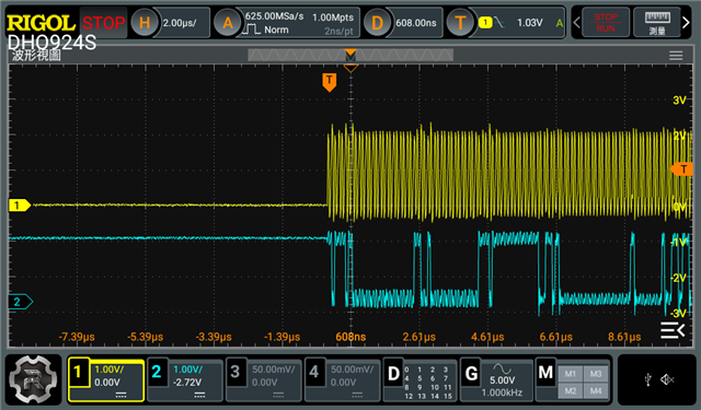
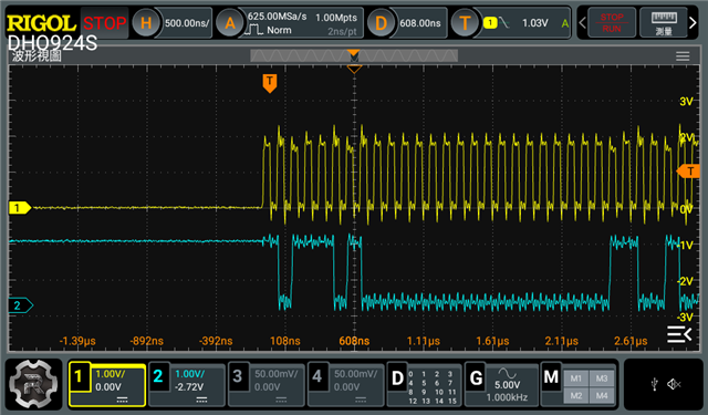
    Yes, we’ve measured the nRST line after the cc33xx and cc33xx_sdio kernel modules are loaded, and it remains HIGH as expected.

    Please find the attached oscilloscope screenshot for reference. It shows the signals right after power-on:

    • Yellow: 1.8V power supply (VDD)

    • Red: nRESET pin (WL_IRQ)

    As shown in the waveform, the nRESET line goes high more than 100 µs after VDD is stable, which we believe should meet the module’s timing requirements.

    Thank you again for your kind support and guidance. Please let us know if you notice anything unusual or if there’s anything else we should check.

  • Hi Chang,

    A few questions.

    1. Can you point me to where I can find the SDK or linux kernel source code for this processor?

    2. Can you remove 'cap-sdio-irq' from your devicetree?

    3. Can you collect the logs from the LOGGER pin? I would like to check that the cc33 device is booting up correctly.

    nRESET pin (WL_IRQ)

    Please note that nRESET and WL_IRQ are not the same pin. nRESET and WL_IRQ should be individually connected to your host MPU, but they should not be connected together. 

  • Thanks again for your continued support. Please see our responses below:

    1. Due to the size of the SDK, we’ve only shared the linux folder.
      Please refer to the following paths in our source tree:

    • Device tree source file:
      linux_6.1.102/arch/arm/boot/dts/hc1725-fpu-agt725-11.dts

    • TI driver source directories:
      linux_6.1.102/drivers/bluetooth/
      linux_6.1.102/drivers/net/wireless/ti/

    We’ve uploaded the folder here:
    https://drive.google.com/file/d/1YsQhNyxZ_B2iWI4G5p76fRRgLAsB0a9v/view?usp=sharing

    1. We’ve removed the cap-sdio-irq property from the device tree, but unfortunately the issue persists, and we’re still seeing the same error messages.

    2. Regarding the LOGGER pin:
      Could you please confirm whether it’s sufficient to connect the LOGGER pin directly to a serial receiver to capture logs?
      Does the baud rate need to be preconfigured, or is it initialized automatically by the CC33xx?
      So far, we’ve probed the LOGGER pin using an oscilloscope, but we haven’t observed any signal activity.

    Lastly, regarding the nRESET pin (WL_IRQ) comment — that was a typo on our part. We confirm that nRESET and WL_IRQ are not connected together. Thank you for pointing that out.

  • Hi Chang,

    Could you please confirm whether it’s sufficient to connect the LOGGER pin directly to a serial receiver to capture logs?
    Does the baud rate need to be preconfigured, or is it initialized automatically by the CC33xx?
    So far, we’ve probed the LOGGER pin using an oscilloscope, but we haven’t observed any signal activity.

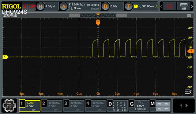
    Yes you only need to connect the LOGGER pin directly to the "RX" pin of a UART-USB converter to connect to your PC. The logger pin is essentially a "UART-TX" pin where the data output is encoded. 

    If you are not seeing any data on the output of this pin then that is concerning. I would check that the power rails are setup correctly and that you have a 40MHz FAST CLK connected. 

  • Also make sure that WL_IRQ is LOW when the radio powers up. This is a Sense On Power pin, and if the host pulls this up or drives it high at power up, the device will not initialize correctly.

  • I will check the power rails and ensure the 40 MHz fast clock is connected properly.

    Just to confirm, if I want to connect the LOGGER pin to the PC-side UART (via USB-to-UART converter), what baud rate should I use? Is it 115200?

    Thanks again for the support!

  • Thank you for the reminder. I will make sure that WL_IRQ is LOW and LOGGER is HIGH during power-up.

  • Hi Chang,

    Just to confirm, if I want to connect the LOGGER pin to the PC-side UART (via USB-to-UART converter), what baud rate should I use? Is it 115200?

    If you're using the simplelink wifi toolbox and logger tool, then the tool will automatically collect and parse the logs and set the baudrate, so there is nothing for you to do.

    Having said that, the baudrate should be set to 3000000.

  • Hi Sabeeh,
    Thanks again for your support.
    Currently, we are still not seeing any output signal from the LOGGER pin.
    We’d like to confirm — if LOGGER has no output at all, does that indicate the chip has not booted up correctly? Should the LOGGER output become active immediately after power-up if the device is functioning normally?

    We've checked the power-up sequence and it seems fine. Our current setup is as follows:

    1. LOGGER is pulled up to 1.8V via a 9.1kΩ resistor. We confirmed it stays at high level (1.8V).

    2. WL_IRQ is directly connected to the SoC (no external resistor), and it stays Low after power-up.

    3. nRESET is also directly connected to the SoC and remains High (1.8V) after power-up.

    4. The main supply voltage to the Wi-Fi chip is confirmed to be 3.3V.

    5. A 40 MHz crystal is connected and running, providing the required FAST_CLK to the IC.

    Could you please help us verify if any of the above might prevent the LOGGER from outputting logs?

  • Hi Chang,

    Sorry for the delay. 

    We’d like to confirm — if LOGGER has no output at all, does that indicate the chip has not booted up correctly? Should the LOGGER output become active immediately after power-up if the device is functioning normally?

    That's correct. If there is no output from LOGGER after power up, then there seems to be a hardware problem. Have you confirmed this with an oscilloscope? 

    Our current setup is as follows:

    As far as I can tell, this setup seems fine. Have you checked the 1.8V and 3.3V rails are correct and CC33xx device is getting powered correctly?