This thread has been locked.

If you have a related question, please click the "Ask a related question" button in the top right corner. The newly created question will be automatically linked to this question.

CC3220MODA: Using IO retention to replace discrete external pull-down during hibernate

Part Number: CC3220MODA
Other Parts Discussed in Thread: CC3235SF, CC3220SF, SYSCONFIG

Tool/software:

After producing a run of hardware for a new design, we discovered a small oversight in the design we're hoping to fix in firmware without having to modify the hardware.

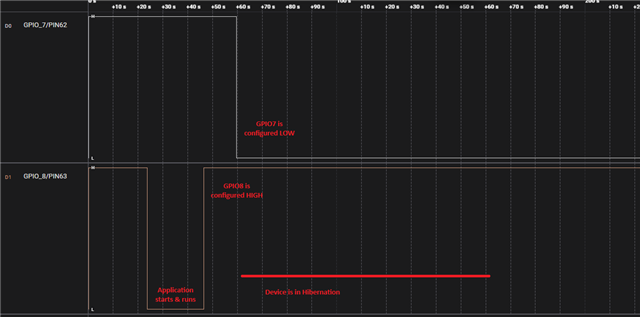
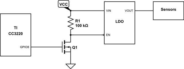
This system primarily stays in hibernate mode but wakes up a few times per hour to take some sensor measurements. Power management for these external sensors is handled by simply turning off their dedicated power supply.

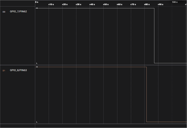
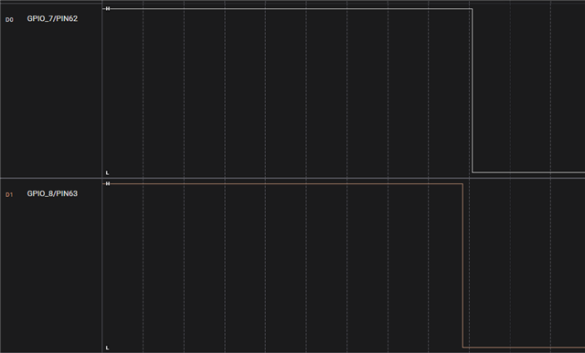
We accidentally omitted the external pull-down on the gate of Q1 necessary to guarantee that the LDO and sensors stay off when the CC3220 is hibernating and GPIO8 is hi-Z. So we're seeing some unpredictable behavior as GPIO8 floats randomly while the CC3220 hibernates.

Reading the CC3220 datasheet and manual, it seems like we should be able to fix this with only firmware by making sure we do the following:

  1. Configure IO retention to include retention group #0, which (of the four groups) is the group containing GPIO8
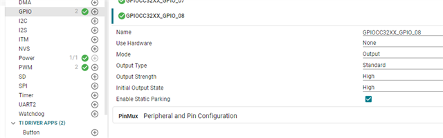
  2. Before hibernating, and immediately before activating IO retention, (re)configure GPIO8 as an input with internal pull-down enabled
  3. After reconfiguring GPIO8 as input w/PD, but before hibernating, activate/enable IO retention
  4. Enter hibernate mode, where the pulled-down state of GPIO8 should be retained for the entire hibernation period

This is our understanding, but after taking a crack (or five) at it ourselves we're not having much success getting the desired result.

Can TI confirm...

  • That it should be possible to resolve this "missing external pull-down causing random behavior during hibernate" issue with only a firmware update?
  • Whether we're missing (or misunderstanding) any critical steps to get this to work as expected?
  • Any common pitfalls/gotchas/drawbacks to using this IO retention functionality?
  • Hi,
    Thanks for reaching out on this topic. Apologize for the delay in the response. 

    Reading the steps you outlined, it seems logical to accomplish this. 

    Can you verify that GPIO8 is staying stable in retention during hibernation? To do this, configure GPIO8 as an output with an internal pull up resistor. This will help to know that the GPIO is stable/configured properly in the hibernation state. 

  • Getting GPIO8 to behave reliably during hibernation is the entire issue. If it did, there wouldn't be any problem to solve here.

    What we have seen is that initially, before trying to control GPIO8 during hibernation, GPIO8 would go into hi-z during hibernation causing unpredictable system performance. Then, after changing the firmware to try to control GPIO8 during hibernation (at least to our best understanding), we see no change to the system behavior. Seems like GPIO8 is still going hi-z during hibernation, like we're missing some critical configuration step or something.

  • Yes. I understand that the GPIO8 is not reliably going LOW in hibernation mode. Since, we can't measure the LOW state in hibernation, we wanted to try measuring the GPIO in 'high' state during hibernation. This would give us the validation on the steps you're following to place GPIO. This was the intent for that request. 

    Can you share the source code for configuring GPIO8 for hibernation (steps 1 to 4 above)? 

  • We can reliably control the state of the GPIO outside of hibernation to drive it high or low, though when actively driven as an output I don't think we would generally enable pull-up or pull-down resistors. We can double-check this to confirm but I don't think the issue has anything to do with GPIO control but more likely has to do with some retention-specific functionality like "retention groups" or how to properly enable retention (as opposed to just hibernating with no retention.)

    I personally am not the firmware engineer on this product but I will get in touch with him to see about sharing some relevant code for review here.

  • Here is the firmware snippet for the configuration and the powerShutdown() call that initiates hibernation with a call to the Power_shutdown() in the library.

    This is the code for our config of GPIO8 and then the modification prior to hibernate to try using the IO retention.  As CJ mentioned, a few different configurations for GPIO8 were tried in addition to the setting: PowerCC32XX_WEAK_PULL_DOWN_STD, including: PowerCC32XX_NO_PULL_HIZ, PowerCC32XX_WEAK_PULL_DOWN_OPENDRAIN, PowerCC32XX_DRIVE_LOW to see if any difference was observed.  The results did not change based on these changes.Also of note, when connecting a digital logic probe to GPIO8 the GPIO8 pin stays low during hibernate as desired.  The logic probe has an impedance of 1Mohm,10pF.  When disconnecting this probe, then the incorrect behavior returns.

    We are running a test now with the .enablePolicy = true to verify the behavior.  The Power_enablePolicy() is called before each measurement currently but will test this behavior out as well.

    GPIO_PinConfig gpioPinConfigs[] = {
        /* input pins with callbacks */
        /* WiFi TH USB Power Monitor */
        GPIOCC32XX_GPIO_17 | GPIO_CFG_IN_PD | GPIO_CFG_IN_INT_FALLING
        /* WiFi TH push button */
        , GPIOCC32XX_GPIO_04 | GPIO_CFG_IN_PD | GPIO_CFG_IN_INT_BOTH_EDGES
        /* WIFI-CO2 - CO2 READY pin */
        , GPIOCC32XX_GPIO_24 | GPIO_CFG_IN_PD | GPIO_CFG_IN_INT_FALLING
        /* Input pins without callbacks */
        /* Output pins */
        /* WiFi TH I2C sensor power */
        , GPIOCC32XX_GPIO_16 | GPIO_CFG_OUT_STD | GPIO_CFG_OUT_STR_HIGH | GPIO_CFG_OUT_LOW
        /* WiFi TH battery measurement switch */
        , GPIOCC32XX_GPIO_06 | GPIO_CFG_OUT_STD | GPIO_CFG_OUT_STR_HIGH | GPIO_CFG_OUT_LOW
        /* WiFi TH board ID */
        , GPIOCC32XX_GPIO_22 | GPIO_CFG_IN_PD | GPIO_CFG_IN_INT_NONE
        , GPIOCC32XX_GPIO_13 | GPIO_CFG_IN_PD | GPIO_CFG_IN_INT_NONE
        , GPIOCC32XX_GPIO_12 | GPIO_CFG_IN_PD | GPIO_CFG_IN_INT_NONE
        /* WIFI-LD - Leak Cable Continuity */
        , GPIOCC32XX_GPIO_07 | GPIO_CFG_OUT_STD | GPIO_CFG_OUT_STR_LOW | GPIO_CFG_OUT_LOW
        /* WIFI-LD - +5.0v Power Enable */
        , GPIOCC32XX_GPIO_08 | GPIO_CFG_OUT_STD | GPIO_CFG_OUT_STR_LOW | GPIO_CFG_OUT_LOW
        /* WIFI-1WIRE - I2C-to-1WIRE Bridge SLPZ pin */
        , GPIOCC32XX_GPIO_28 | GPIO_CFG_OUT_STD | GPIO_CFG_OUT_STR_LOW | GPIO_CFG_OUT_LOW
    };
    PowerCC32XX_ParkInfo parkInfo[] = {
    /*          PIN                    PARK STATE              PIN ALIAS (FUNCTION)
         -----------------  ------------------------------     -------------------- */
        {PowerCC32XX_PIN01, PowerCC32XX_WEAK_PULL_DOWN_STD}, /* GPIO10              */
        {PowerCC32XX_PIN02, PowerCC32XX_WEAK_PULL_DOWN_STD}, /* GPIO11              */
        {PowerCC32XX_PIN03, PowerCC32XX_WEAK_PULL_DOWN_STD}, /* GPIO12              */
        {PowerCC32XX_PIN04, PowerCC32XX_WEAK_PULL_DOWN_STD}, /* GPIO13              */
        {PowerCC32XX_PIN05, PowerCC32XX_WEAK_PULL_DOWN_STD}, /* GPIO14              */
        {PowerCC32XX_PIN06, PowerCC32XX_WEAK_PULL_DOWN_STD}, /* GPIO15              */
        {PowerCC32XX_PIN07, PowerCC32XX_WEAK_PULL_DOWN_STD}, /* GPIO16              */
        {PowerCC32XX_PIN08, PowerCC32XX_WEAK_PULL_DOWN_STD}, /* GPIO17              */
        {PowerCC32XX_PIN13, PowerCC32XX_WEAK_PULL_DOWN_STD}, /* FLASH_SPI_DIN       */
        {PowerCC32XX_PIN15, PowerCC32XX_WEAK_PULL_DOWN_STD}, /* GPIO22              */
        {PowerCC32XX_PIN16, PowerCC32XX_WEAK_PULL_DOWN_STD}, /* TDI (JTAG DEBUG)    */
        {PowerCC32XX_PIN17, PowerCC32XX_WEAK_PULL_DOWN_STD}, /* TDO (JTAG DEBUG)    */
        {PowerCC32XX_PIN19, PowerCC32XX_WEAK_PULL_DOWN_STD}, /* TCK (JTAG DEBUG)    */
        {PowerCC32XX_PIN20, PowerCC32XX_WEAK_PULL_DOWN_STD}, /* TMS (JTAG DEBUG)    */
        {PowerCC32XX_PIN18, PowerCC32XX_WEAK_PULL_DOWN_STD}, /* GPIO28              */
        {PowerCC32XX_PIN21, PowerCC32XX_WEAK_PULL_DOWN_STD}, /* SOP2                */
        {PowerCC32XX_PIN29, PowerCC32XX_WEAK_PULL_DOWN_STD}, /* ANTSEL1             */
        {PowerCC32XX_PIN30, PowerCC32XX_WEAK_PULL_DOWN_STD}, /* ANTSEL2             */
        {PowerCC32XX_PIN45, PowerCC32XX_WEAK_PULL_DOWN_STD}, /* DCDC_ANA2_SW_P      */
        {PowerCC32XX_PIN50, PowerCC32XX_WEAK_PULL_DOWN_STD}, /* GPIO0               */
        {PowerCC32XX_PIN52, PowerCC32XX_WEAK_PULL_DOWN_STD}, /* RTC_XTAL_N          */
        {PowerCC32XX_PIN53, PowerCC32XX_WEAK_PULL_DOWN_STD}, /* GPIO30              */
        {PowerCC32XX_PIN55, PowerCC32XX_WEAK_PULL_DOWN_STD}, /* GPIO1 (XDS_UART_RX) */
        {PowerCC32XX_PIN57, PowerCC32XX_WEAK_PULL_DOWN_STD}, /* GPIO2 (XDS_UART_TX) */
        {PowerCC32XX_PIN58, PowerCC32XX_WEAK_PULL_DOWN_STD}, /* GPIO3               */
        {PowerCC32XX_PIN59, PowerCC32XX_WEAK_PULL_DOWN_STD}, /* GPIO4               */
        {PowerCC32XX_PIN60, PowerCC32XX_WEAK_PULL_DOWN_STD}, /* GPIO5               */
        {PowerCC32XX_PIN61, PowerCC32XX_WEAK_PULL_DOWN_STD}, /* GPIO6               */
        {PowerCC32XX_PIN62, PowerCC32XX_WEAK_PULL_DOWN_STD}, /* GPIO7               */
        {PowerCC32XX_PIN63, PowerCC32XX_WEAK_PULL_DOWN_STD}, /* GPIO8               */
        {PowerCC32XX_PIN64, PowerCC32XX_WEAK_PULL_DOWN_STD}, /* GPIO9               */
    };
    /*
     *  This structure defines the configuration for the Power Manager.
     *
     *  In this configuration the Power policy is disabled by default (because
     *  enablePolicy is set to false).  The Power policy can be enabled dynamically
     *  at runtime by calling Power_enablePolicy(), or at build time, by changing
     *  enablePolicy to true in this structure.
     */
    const PowerCC32XX_ConfigV1 PowerCC32XX_config = {
        .policyInitFxn = &PowerCC32XX_initPolicy,
        .policyFxn = &PowerCC32XX_sleepPolicy,
        .enterLPDSHookFxn = NULL,
        .resumeLPDSHookFxn = NULL,
        .enablePolicy = false,
        .enableGPIOWakeupLPDS = true,
        .enableGPIOWakeupShutdown = true,
        .enableNetworkWakeupLPDS = true,
        .wakeupGPIOSourceLPDS = PRCM_LPDS_GPIO2,    // UART RX
        .wakeupGPIOTypeLPDS = PRCM_LPDS_RISE_EDGE,
        .wakeupGPIOFxnLPDS = NULL,
        .wakeupGPIOFxnLPDSArg = 0,
        .wakeupGPIOSourceShutdown = PRCM_HIB_GPIO4, // push button
        .wakeupGPIOTypeShutdown = PRCM_HIB_RISE_EDGE,
        .ramRetentionMaskLPDS = PRCM_SRAM_COL_1 | PRCM_SRAM_COL_2 |
            PRCM_SRAM_COL_3 | PRCM_SRAM_COL_4,
        .keepDebugActiveDuringLPDS = false,
        .ioRetentionShutdown = PRCM_IO_RET_GRP_0 | PRCM_IO_RET_GRP_1,
        .pinParkDefs = parkInfo,
        .numPins = sizeof(parkInfo) / sizeof(PowerCC32XX_ParkInfo)
    };
    void powerShutdown(uint32_t shutdownTime)
    {
    #ifdef CC32XX
        Power_NotifyObj hibSignal;
    #endif
    #ifdef __MSP432P401R__
    #if 0
        Power_registerNotify(&hibSignal, PowerMSP432_ENTERING_SHUTDOWN,
                             preHibConfig,
                             (uintptr_t)NULL);
        if(shutdownTime != MAX_INT)
        {
            /* config gpio to wakeup from hib */
        }
        /*
         *    PowerMSP432_SHUTDOWN_0 => PCM_LPM35_VCORE0
         *    PowerMSP432_SHUTDOWN_1 => PCM_LPM45
         */
        Power_shutdown(PowerMSP432_SHUTDOWN_0,0);
    #else
        if(shutdownTime != MAX_INT)
        {
            if(shutdownTime >= 1000)
            {
                sleep(shutdownTime / 1000);
            }
            usleep((shutdownTime % 1000) * 1000);
        }
    #endif
    #endif
    #ifdef CC32XX
        // modify GPIO8 config for CO2 sensor
        GPIO_PinConfig gpiocfg = GPIOCC32XX_GPIO_08 | GPIO_CFG_IN_PD | GPIO_CFG_IN_INT_NONE;
        GPIO_setConfig(9, gpiocfg);
        Power_registerNotify(&hibSignal, PowerCC32XX_ENTERING_SHUTDOWN,
                             preHibConfig,
                             (uintptr_t)NULL);
        Power_shutdown(0,shutdownTime);
    #endif
    }

  • Making a new, parallel thread because I don't want to derail the main conversation...

    But another good way to crack this would be for somebody at TI to make a very simple project which targets one of their SimpleLink LaunchPad dev kits, where all the project does is configure GPIO8 for pull-down IO retention and then go straight into HIB forever.

    Then TI would validate electrically that it functions as intended (a ~10MΩ external pull-up on GPIO8?), and share the project file(s) with us. Then we buy the same dev kit, reproduce the demo exactly, validate for ourselves, then migrate the functionality into our application.

  • Hi Alan,
    Can you try 'GPIOCC32XX_CFG_USE_STATIC' for the gpio config?

    In order to 'park' the pin in the state statically defined in PowerCC32XX_config.pinParkDefs[] table, this configuration needs to be defined. Can you please try this and let me know? 

  • Yes, I will make that change prior to my test.

  • I don't have that define in our sdk library.  simplelink_cc32xx_sdk_2_40_00_05.

  • You can try 'GPIOCC32XX_USE_STATIC' this define. It looks like it was renamed. 


    software-dl.ti.com/.../group___g_p_i_o_c_c32_x_x___pin_config_ids.html

  • Got it, thanks! 

  • That did not change the behavior.  The GPIO8 does not stay low during hibernate.

  • Hi Alan,

    Thanks for the test results on that. That is disappointing! 
    Are you able to try the following? 

    Can you verify that GPIO8 is staying HIGH in retention during hibernation? To do this, configure GPIO8 as an output with an internal pull up resistor. This will help to know that the GPIO is configured properly in the hibernation state with the steps you're following. As you noted earlier, the impedance of the logic probe influences the output reading, when it is attempted to drive low. 
    I confirmed that you're using the correct retention groups for GPIO8. Will discuss this with a HW engineer and follow up as well. 

  • Can you also double check the following?

    In powerShutdown() function, where you set the configuration for GPIO8. Can you confirm that '9' is the correct entry?
    I'm referring to this line:

    GPIO_setConfig(9, gpiocfg);

  • in the code above for gpioPinConfigs[], if I'm correct, the lines 4,6,8,12,14,16,18,20,22 are the indexes for the configs 0-9 with line 22 being GPIO8.  I think that is correct.

  • Ok. But, I was referring to line 124 (GPIO_setConfig(9, gpiocfg);)
    Please double check first parameter for GPIO_set() function. 

  • right, in GPIO_setConfig it references PinConfig     *config = (PinConfig *) &GPIOCC32XX_config.pinConfigs[index];  which is the pin configs listed in the post above starting at line 1 which is the index 9 into that config.

  • Ok. 
    For line 123, GPIO_PinConfig gpiocfg = GPIOCC32XX_GPIO_08 | GPIO_CFG_IN_PD | GPIO_CFG_IN_INT_NONE;

    We do not include GPIO index as part of the config. Can you try without the index (and only with Pull down and init none)?
    GPIO_PinConfig gpiocfg = GPIO_CFG_IN_PD | GPIO_CFG_IN_INT_NONE;

  • Yes, I can try that.  It will be a bit.

  • Hi Alan,
    Any update on this? Did you get a chance to try this? 
    Make sure to use 'GPIOCC32XX_USE_STATIC' for GPIO config as well, along with this change. 

  • I did get a chance to try this now, this did not change the behavior either.  Bummer.

  • Hi Alan,

    Sorry, for the late response. I was trying to reproduce this on our side with a CC3235SF launch pad. I'm able to see the behavior with GPIO being configured as an input and driven low. In this scenario, it doesn't look the PIN is driven to low in hibernation. 

    But, we can place the GPIO in LOW if we configure the PIN as an output and use the internal pull down resistor.

    Is this something that you already tried?  If not, can you try the below in powerShutdown() function?

    GPIO_PinConfig gpiocfg = GPIOCC32XX_GPIO_08| GPIO_CFG_OUTPUT_INTERNAL | GPIO_CFG_PULL_DOWN_INTERNAL | GPIOCC32XX_CFG_USE_STATIC;

    With this, we're able to see that the GPIO is in LOW for hibernation. 

  • I didn't try that exact configuration because our version does not have the GPIO_CFG_OUTPUT_INTERNAL or GPIO_CFG_PULL_DOWN_INTERNAL defines.  I'm guessing they are just worded differently in our version so I'll search for it.

  • Below are similar to what I used. Try below 2 options.

    1. GPIO_CFG_OUTPUT and GPIO_CFG_OUT_OD_PD
    2. GPIO_CFG_OUTPUT and GPIO_CFG_OUT_LOW
  • Thanks for finding those, I will give those a try.

  • Hi Alan,

    Were you able to try this? Any update? 

  • Yes, sorry I was able to try that but forgot to respond.  This did not change the results either.

  • Okay. Can you please share the exact code snippet(s) for GPIO_8 that you're using? For GPIO pin config, park info, and PowerCC32XX_config? 

  • Hi Alan,

    Tried the same experiment with CC3220SF launch pad and one of the examples (pwmled2) in the SDK on our side. I'm able to see that the GPIO is changed to LOW right before retention and it stays in LOW during retention.

    Here are the steps. Do you have CC3220SF launch pad to try this on your side?

    1. Import pwmled2 example to CCS
    2. Open pwmled2.syscfg in CCS (GUI) and open GPIO module
    3. Add GPIO_8 and map it to PIN62 on the header. Configure GPIO_8 as follows
      1. Mode - Output
      2. Output Type - Standard
      3. Output Strength - High
      4. Initial Output State - High
      5. Enable Static Parking - Checked
    4. Go to Power module in Sysconfig UI
      1. IO Rentention Shutdown - GRP_0 and GRP_1 are selected
      2. Pin Park States do not need to be changed
    5. Add code change in the mainThread to trigger hibernation
      1. call powerShutdown() in the mainThread
      2. Define powerShutdown() as follows
      3. int preHibConfig(unsigned int eventType,
                         uintptr_t eventArg,
                         uintptr_t clientArg)
        {
            return(Power_SOK);
        }
        
        void powerShutdown(uint32_t shutdownTime)
        {
            Power_NotifyObj hibSignal;
        
            GPIO_PinConfig gpiocfg = GPIOCC32XX_GPIO_08| GPIO_CFG_OUTPUT_INTERNAL | GPIO_CFG_PULL_DOWN_INTERNAL | GPIOCC32XX_CFG_USE_STATIC;
            GPIO_setConfig(8, gpiocfg);
        
            Power_registerNotify(&hibSignal, PowerCC32XX_ENTERING_SHUTDOWN,
                                 preHibConfig,
                                 (uintptr_t)NULL);
            Power_shutdown(0,shutdownTime);
        }
        
    6. When the example is run on the launch pad, device configures GPIO in LOW state and goes to retention
      1. In my example, I've added 2 GPIOS (GPIO 7 and GPIO 8). Both behaved correctly. 
    7. For reference, code from ti_drivers_config.c. parkInfo[] was not changed from the default settings. But, here it is for reference.
      1. /*
         *  ======== gpioPinConfigs ========
         *  Array of Pin configurations
         */
        GPIO_PinConfig gpioPinConfigs[33] = {
            GPIO_CFG_INPUT | GPIOCC32XX_DO_NOT_CONFIG,
            GPIO_CFG_INPUT | GPIOCC32XX_DO_NOT_CONFIG,
            GPIO_CFG_INPUT | GPIOCC32XX_DO_NOT_CONFIG,
            GPIO_CFG_INPUT | GPIOCC32XX_DO_NOT_CONFIG,
            GPIO_CFG_INPUT | GPIOCC32XX_DO_NOT_CONFIG,
            GPIO_CFG_INPUT | GPIOCC32XX_DO_NOT_CONFIG,
            GPIO_CFG_INPUT | GPIOCC32XX_DO_NOT_CONFIG,
            GPIO_CFG_OUTPUT_INTERNAL | GPIO_CFG_OUT_STR_HIGH | GPIO_CFG_OUT_HIGH | GPIOCC32XX_CFG_USE_STATIC, /* GPIOCC32XX_GPIO_07 */
            GPIO_CFG_OUTPUT_INTERNAL | GPIO_CFG_OUT_STR_HIGH | GPIO_CFG_OUT_HIGH | GPIOCC32XX_CFG_USE_STATIC, /* GPIOCC32XX_GPIO_08 */
            GPIO_CFG_INPUT | GPIOCC32XX_DO_NOT_CONFIG,
            GPIO_CFG_INPUT | GPIOCC32XX_DO_NOT_CONFIG,
            GPIO_CFG_INPUT | GPIOCC32XX_DO_NOT_CONFIG,
            GPIO_CFG_INPUT | GPIOCC32XX_DO_NOT_CONFIG,
            GPIO_CFG_INPUT | GPIOCC32XX_DO_NOT_CONFIG,
            GPIO_CFG_INPUT | GPIOCC32XX_DO_NOT_CONFIG,
            GPIO_CFG_INPUT | GPIOCC32XX_DO_NOT_CONFIG,
            GPIO_CFG_INPUT | GPIOCC32XX_DO_NOT_CONFIG,
            GPIO_CFG_INPUT | GPIOCC32XX_DO_NOT_CONFIG,
            GPIOCC32XX_DO_NOT_CONFIG, /* Pin not available */
            GPIOCC32XX_DO_NOT_CONFIG, /* Pin not available */
            GPIOCC32XX_DO_NOT_CONFIG, /* Pin not available */
            GPIOCC32XX_DO_NOT_CONFIG, /* Pin not available */
            GPIO_CFG_INPUT | GPIOCC32XX_DO_NOT_CONFIG,
            GPIO_CFG_INPUT | GPIOCC32XX_DO_NOT_CONFIG,
            GPIO_CFG_INPUT | GPIOCC32XX_DO_NOT_CONFIG,
            GPIO_CFG_INPUT | GPIOCC32XX_DO_NOT_CONFIG,
            GPIO_CFG_INPUT | GPIOCC32XX_DO_NOT_CONFIG,
            GPIO_CFG_INPUT | GPIOCC32XX_DO_NOT_CONFIG,
            GPIO_CFG_INPUT | GPIOCC32XX_DO_NOT_CONFIG,
            GPIO_CFG_INPUT | GPIOCC32XX_DO_NOT_CONFIG,
            GPIO_CFG_INPUT | GPIOCC32XX_DO_NOT_CONFIG,
            GPIO_CFG_INPUT | GPIOCC32XX_DO_NOT_CONFIG,
            GPIO_CFG_INPUT | GPIOCC32XX_DO_NOT_CONFIG,
        };
        
        PowerCC32XX_ParkInfo parkInfo[];
        /*
         *  This structure defines the configuration for the Power Manager.
         */
        const PowerCC32XX_ConfigV1 PowerCC32XX_config = {
            .policyInitFxn             = PowerCC32XX_initPolicy,
            .policyFxn                 = PowerCC32XX_sleepPolicy,
            .enterLPDSHookFxn          = NULL,
            .resumeLPDSHookFxn         = NULL,
            .enablePolicy              = false,
            .enableGPIOWakeupLPDS      = true,
            .enableGPIOWakeupShutdown  = true,
            .enableNetworkWakeupLPDS   = true,
            .wakeupGPIOSourceLPDS      = PRCM_LPDS_GPIO13,
            .wakeupGPIOTypeLPDS        = PRCM_LPDS_FALL_EDGE,
            .wakeupGPIOFxnLPDS         = NULL,
            .wakeupGPIOFxnLPDSArg      = 0,
            .wakeupGPIOSourceShutdown  = PRCM_HIB_GPIO13,
            .wakeupGPIOTypeShutdown    = PRCM_HIB_RISE_EDGE,
            .ramRetentionMaskLPDS      = PRCM_SRAM_COL_1|PRCM_SRAM_COL_2|PRCM_SRAM_COL_3|PRCM_SRAM_COL_4,
            .latencyForLPDS            = 20000,
            .keepDebugActiveDuringLPDS = false,
            .ioRetentionShutdown       = PRCM_IO_RET_GRP_0|PRCM_IO_RET_GRP_1,
            .pinParkDefs               = parkInfo,
            .numPins                   = 31
        };
        
        /*
         * This table defines the parking state to be set for each parkable pin
         * during LPDS. (Device resources must be parked during LPDS to achieve maximum
         * power savings.)  If the pin should be left unparked, specify the state
         * PowerCC32XX_DONT_PARK.  For example, for a UART TX pin, the device
         * will automatically park the pin in a high state during transition to LPDS,
         * so the Power Manager does not need to explictly park the pin.  So the
         * corresponding entries in this table should indicate PowerCC32XX_DONT_PARK.
         */
        PowerCC32XX_ParkInfo parkInfo[] = {
        /*        PIN                    PARK STATE              Pin Alias
           -----------------  ------------------------------     ---------------*/
        
          {PowerCC32XX_PIN01, PowerCC32XX_WEAK_PULL_DOWN_STD},   /* GP10 */
          {PowerCC32XX_PIN02, PowerCC32XX_WEAK_PULL_DOWN_STD},   /* GP11 */
          {PowerCC32XX_PIN03, PowerCC32XX_WEAK_PULL_DOWN_STD},   /* GP12 */
          {PowerCC32XX_PIN04, PowerCC32XX_WEAK_PULL_DOWN_STD},   /* GP13 */
          {PowerCC32XX_PIN05, PowerCC32XX_WEAK_PULL_DOWN_STD},   /* GP14 */
          {PowerCC32XX_PIN06, PowerCC32XX_WEAK_PULL_DOWN_STD},   /* GP15 */
          {PowerCC32XX_PIN07, PowerCC32XX_WEAK_PULL_DOWN_STD},   /* GP16 */
          {PowerCC32XX_PIN08, PowerCC32XX_WEAK_PULL_DOWN_STD},   /* GP17 */
          {PowerCC32XX_PIN13, PowerCC32XX_WEAK_PULL_DOWN_STD},
          {PowerCC32XX_PIN15, PowerCC32XX_WEAK_PULL_DOWN_STD},   /* GP22 */
          {PowerCC32XX_PIN16, PowerCC32XX_WEAK_PULL_DOWN_STD},   /* TDI */
          {PowerCC32XX_PIN17, PowerCC32XX_WEAK_PULL_DOWN_STD},   /* TDO */
          {PowerCC32XX_PIN18, PowerCC32XX_WEAK_PULL_DOWN_STD},   /* GP28 */
          {PowerCC32XX_PIN19, PowerCC32XX_WEAK_PULL_DOWN_STD},   /* TCK */
          {PowerCC32XX_PIN20, PowerCC32XX_WEAK_PULL_DOWN_STD},   /* TMS */
          {PowerCC32XX_PIN21, PowerCC32XX_WEAK_PULL_DOWN_STD},   /* SOP2 */
          {PowerCC32XX_PIN29, PowerCC32XX_WEAK_PULL_DOWN_STD},   /* GP26 */
          {PowerCC32XX_PIN30, PowerCC32XX_WEAK_PULL_DOWN_STD},   /* GP27 */
          {PowerCC32XX_PIN45, PowerCC32XX_WEAK_PULL_DOWN_STD},   /* GP31 */
          {PowerCC32XX_PIN50, PowerCC32XX_WEAK_PULL_DOWN_STD},   /* GP00 */
          {PowerCC32XX_PIN52, PowerCC32XX_WEAK_PULL_DOWN_STD},   /* GP32 */
          {PowerCC32XX_PIN53, PowerCC32XX_WEAK_PULL_DOWN_STD},   /* GP30 */
          {PowerCC32XX_PIN55, PowerCC32XX_WEAK_PULL_UP_STD},   /* GP01 */
          {PowerCC32XX_PIN57, PowerCC32XX_WEAK_PULL_UP_STD},   /* GP02 */
          {PowerCC32XX_PIN58, PowerCC32XX_WEAK_PULL_DOWN_STD},   /* GP03 */
          {PowerCC32XX_PIN59, PowerCC32XX_WEAK_PULL_DOWN_STD},   /* GP04 */
          {PowerCC32XX_PIN60, PowerCC32XX_WEAK_PULL_DOWN_STD},   /* GP05 */
          {PowerCC32XX_PIN61, PowerCC32XX_WEAK_PULL_DOWN_STD},   /* GP06 */
          {PowerCC32XX_PIN62, PowerCC32XX_WEAK_PULL_DOWN_STD},   /* GP07 */
          {PowerCC32XX_PIN63, PowerCC32XX_WEAK_PULL_DOWN_STD},   /* GP08 */
          {PowerCC32XX_PIN64, PowerCC32XX_WEAK_PULL_DOWN_STD},   /* GP09 */
        };
  • We really appreciated your support on this Santhosh, I'm sure Alan will get back to you on it shortly.

    But I have one question about your test setup. When you set up GPIO7/8 for low retention and measured them with your logic analyzer, did you add a very weak (~1-10MΩ?) external pull-UP to those pins?

    The logic analyzer itself is going to be ground-referenced, which means simply connecting it to any particular pin effectively adds a weak pull-down to that pin. So regardless of whether retention is working (holding the GPIO low during HIB) or not working (floating the GPIO during HIB), you will see the same result on your scope captures because the scope itself biases the GPIO towards ground.

    I think the only way to prove specifically that retention is working is to very weakly pull the GPIO in the opposite direction of your retention state, and see that during HIB the MCU overcomes this external bias and holds the GPIO in the correct desired state.

  • For earlier measurement, I did NOT have any external pull-UP resistors on those pins. 

    BUT, just tried having internal pull up on those GPIOS (GPIO 7 and 8). This is configured via Sysconfig and produces ti_drivers_config.c changes as below (PowerCC32XX_WEAK_PULL_UP_STD). If you look at PowerCC32XX_PIN62, and PowerCC32XX_PIN63 from my last post, you'll see the difference. 

    PowerCC32XX_ParkInfo parkInfo[] = {
    /*        PIN                    PARK STATE              Pin Alias
       -----------------  ------------------------------     ---------------*/
    
      {PowerCC32XX_PIN01, PowerCC32XX_WEAK_PULL_DOWN_STD},   /* GP10 */
      {PowerCC32XX_PIN02, PowerCC32XX_WEAK_PULL_DOWN_STD},   /* GP11 */
      {PowerCC32XX_PIN03, PowerCC32XX_WEAK_PULL_DOWN_STD},   /* GP12 */
      {PowerCC32XX_PIN04, PowerCC32XX_WEAK_PULL_DOWN_STD},   /* GP13 */
      {PowerCC32XX_PIN05, PowerCC32XX_WEAK_PULL_DOWN_STD},   /* GP14 */
      {PowerCC32XX_PIN06, PowerCC32XX_WEAK_PULL_DOWN_STD},   /* GP15 */
      {PowerCC32XX_PIN07, PowerCC32XX_WEAK_PULL_DOWN_STD},   /* GP16 */
      {PowerCC32XX_PIN08, PowerCC32XX_WEAK_PULL_DOWN_STD},   /* GP17 */
      {PowerCC32XX_PIN13, PowerCC32XX_WEAK_PULL_DOWN_STD},
      {PowerCC32XX_PIN15, PowerCC32XX_WEAK_PULL_DOWN_STD},   /* GP22 */
      {PowerCC32XX_PIN16, PowerCC32XX_WEAK_PULL_DOWN_STD},   /* TDI */
      {PowerCC32XX_PIN17, PowerCC32XX_WEAK_PULL_DOWN_STD},   /* TDO */
      {PowerCC32XX_PIN18, PowerCC32XX_WEAK_PULL_DOWN_STD},   /* GP28 */
      {PowerCC32XX_PIN19, PowerCC32XX_WEAK_PULL_DOWN_STD},   /* TCK */
      {PowerCC32XX_PIN20, PowerCC32XX_WEAK_PULL_DOWN_STD},   /* TMS */
      {PowerCC32XX_PIN21, PowerCC32XX_WEAK_PULL_DOWN_STD},   /* SOP2 */
      {PowerCC32XX_PIN29, PowerCC32XX_WEAK_PULL_DOWN_STD},   /* GP26 */
      {PowerCC32XX_PIN30, PowerCC32XX_WEAK_PULL_DOWN_STD},   /* GP27 */
      {PowerCC32XX_PIN45, PowerCC32XX_WEAK_PULL_DOWN_STD},   /* GP31 */
      {PowerCC32XX_PIN50, PowerCC32XX_WEAK_PULL_DOWN_STD},   /* GP00 */
      {PowerCC32XX_PIN52, PowerCC32XX_WEAK_PULL_DOWN_STD},   /* GP32 */
      {PowerCC32XX_PIN53, PowerCC32XX_WEAK_PULL_DOWN_STD},   /* GP30 */
      {PowerCC32XX_PIN55, PowerCC32XX_WEAK_PULL_UP_STD},   /* GP01 */
      {PowerCC32XX_PIN57, PowerCC32XX_WEAK_PULL_UP_STD},   /* GP02 */
      {PowerCC32XX_PIN58, PowerCC32XX_WEAK_PULL_DOWN_STD},   /* GP03 */
      {PowerCC32XX_PIN59, PowerCC32XX_WEAK_PULL_DOWN_STD},   /* GP04 */
      {PowerCC32XX_PIN60, PowerCC32XX_WEAK_PULL_DOWN_STD},   /* GP05 */
      {PowerCC32XX_PIN61, PowerCC32XX_WEAK_PULL_DOWN_STD},   /* GP06 */
      {PowerCC32XX_PIN62, PowerCC32XX_WEAK_PULL_UP_STD},   /* GP07 */
      {PowerCC32XX_PIN63, PowerCC32XX_WEAK_PULL_UP_STD},   /* GP08 */
      {PowerCC32XX_PIN64, PowerCC32XX_WEAK_PULL_DOWN_STD},   /* GP09 */
    };

    Results are the same. Logic analyzer shows both GPIO 7 and 8 are driven to LOW and kept in LOW in retention state.

    Hope this helps to verify it on your side. Are you able to try this on your side? 

  • Hi Santhosh,

    Sorry I was out sick, I was able to try this with the same results we've had here.  As CJ mentioned, having the analyzer connected changes the results also.  If I connect a logic analyzer and run the test it will work.  When I disconnect the analyzer and monitor from the other side of the transistor the results are bad.

    I do not have a launchpad board to try this with.

    Thanks,

    Alan

  • Hi Alan, CJ,

    I discussed this with our HW engineer and he agreed that the logic analyzer can influence the logic level (LOW) as we're measuring the GPIO. Recommendation was to try a test to drive the GPIO to HIGH in Hibernation and see if the Driver can drive/keep the signal in HIGH state during hibernation. 

    From this experiment, first I was seeing that the GPIO was not staying HIGH level in hibernation with internal PULL up only. GPIO8 would temporarily change to HIGH but was driven LOW immediately and in hibernation. 

    But, after applying the driver (GPIO_CFG_OUT_HIGH), GPIO8 held in HIGH in hibernation!  See below screen capture. In my experiment, GPIO7 was driven LOW (with internal pull down), but GPIO8 was driven HIGH (with GPIO_CFG_OUT_HIGH) in hibernation. 

    Based on this finding, we can reverse the logic levels for your scenario. Can you try the following on your side?

    Update powerShutdown() to have GPIO8 configured as below?

    GPIO_PinConfig gpiocfg = GPIOCC32XX_GPIO_08| GPIO_CFG_OUTPUT_INTERNAL | GPIO_CFG_OUT_LOW | GPIOCC32XX_CFG_USE_STATIC;

    GPIO8 configured as an output for the application.

    Let us know if that helps or not. 

  • Hi Alan,

    Hope you are doing well. Did you have a chance to try this?