This thread has been locked.

If you have a related question, please click the "Ask a related question" button in the top right corner. The newly created question will be automatically linked to this question.

CC3301MOD: There is little documentation available for CC3301MOD, so please provide details on its specifications.

Expert 2590 points
Part Number: CC3301MOD
Other Parts Discussed in Thread: CC3301

Tool/software:

Hi All,

There is little documentation available for CC3301MOD, so please provide details on its specifications.

1. Interrupts

https://www.ti.com/jp/lit/an/swra779/swra779.pdf 

・It is unclear when interrupts occur.
・It is unclear how to obtain interrupt factors.
・It is unclear whether interrupts can be masked.

2. Cmd, Addr

• The detailed format of CMD and Addr is unclear.
• In the above documentation, Addr appears to be 16 bits, but in the sample project, it appears to be 17 bits.
• The list of CMDs is unclear.
• The specifications for Addr are unclear (does the value of Addr depend on the CMD?).

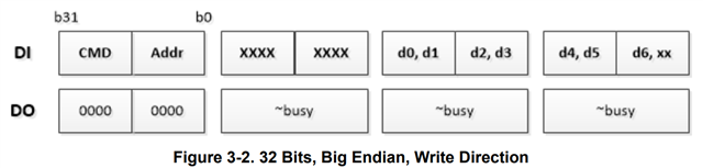
3. Protocol Structure

・Does the above Protocol Structure correspond to the data section (d0, d1, ... d6, xx) in Figure 3-2?
・The specifications for SYNC are unclear (size, fixed value, but the specific value)
・The specifications for Opecode are unclear (size, list of Opecodes)
・The format appears to differ from the sample project. We would like to know the correct specifications.

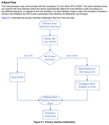
After initial processing is complete, the specification states that firmware is downloaded from the host to the CC3301MOD.
We have confirmed that the above flow is implemented in the sample project.

4. Firmware Download

・Is this download process required every time the power is turned on?
 Is it not possible to save the firmware to CC3301?
 For example, is it not possible to download and save the firmware to CC3301 only once initially, and then continue to operate with the downloaded firmware even after a power restart?

  • Hi,

    See answers below.

    1. Interrupts: interrupts occur whenever the chip has something pending for the host. Could be events, command complete or data.
      Interrupts should not be masked in general although there is a part in the host driver code during initialization that disable and then enable interrupts. You do not have to touch it.
    2. CMD, ADDR: there are 3 values possible for the ADDR, 0xBFF0, 0xBFF8 and 0xBFFC. 0xBFFC is for reading the status register and it is triggered every time the host get an interrupt from the chip. In return the interrupt would get de-asserted. 0xBFF0 is used whenever the host wants to send/receive something (command/data) and 0xBFF8 is triggered right after the 0xBFFC to read more data from the shared memory (since core register is not carrying much information). These can be found under nab.h header file. You can also find the format of these 4 bytes under bus_spi.h header file. The division is not 2 bytes each, it is just a rough division. Address is 17 bites, CMD is 12 bits and all the rest you can find on the header file.
      I agree that CMD is misleading here, it is not actual command but a combination of flags and 12 bits of length.
      It will be fixed for next revision.
    3. yes, the rest goes into what the picture shows as d0, d1, ... 
      SYNC values can be found in nab.h header as HOST_SYNC_PATTERN and DEVICE_SYNC_PATTERN. You will see HOST_SYNC_PATTERN when the host transmits to the chip and DEVICE_SYNC_PATTERN on the other direction.
      Opcodes can be found in Command_e under osprey_public_commands.h header. it is 2 bytes long.
      Not sure what you refer to when you say "differ from the sample project".
    4. yes, every time the device is powered on, the programming is needed since this device is RAM based.

    Regards,

    Shlomi