This thread has been locked.

If you have a related question, please click the "Ask a related question" button in the top right corner. The newly created question will be automatically linked to this question.

CC3220SF: DMA based transfers from SPI being triggered from a timer

Part Number: CC3220SF


Tool/software:

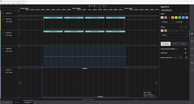
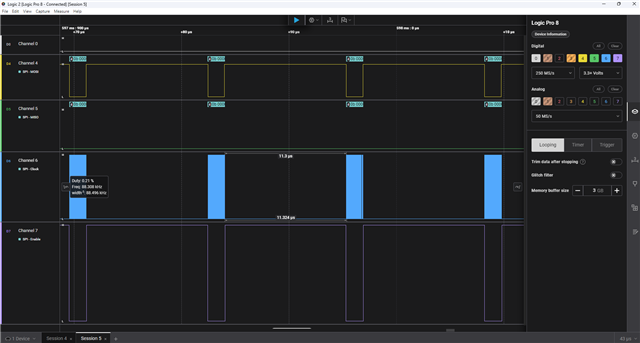
We have an external ADC that provides 32bit data (2 back to back 16bit values) back over SPI.  There is a driver level delay that limits us to about 30us between samples. We have looked a few times at using a timer to Trigger the SPI to transfer data via DMA into memory. We have not been able to figure this out. It seems that some details in the datasheet are not fully worked out. There are some "signals" that should be able to do the triggers, but it is not clear how to fully map the setup. Some details are called out in descriptions of setup, but then not found in register map details. 


It might be that it is not possible but would like to check with those that have deeper knowledge before we totally give up.  We are currently using a PWM to trigger the ADC. This allows us to adjust the timing as we need to change when we need samples.  The goal of using the DMA would be to load data directly into memory and then use CPU cycle to check if we want to keep data or skip data. Also if we could get down to about 5us between samples that would be useful. 10us would be workable. 

  • Hi Ken,

    Just so I understand your setup, you are using DMA to transfer a buffer of ADC values into memory which come in via SPI, and you collect these values at certain times via PWM but are limited to waiting 30us before taking the next sample?

    I'm also trying to figure out your use of a timer; it seems like you are trying to trigger a SPI transaction to transfer data via DMA into memory but I am not sure what this means.

    Additional details and clarity would be helpful.

    Thank you.

    Brandon Liu

  • Hi Ken,

    Based on my understanding of your system, you are using an external ADC which communicates data to the CC3220SF over SPI, and it sounds like you are limited to having 30 microsecond intervals between SPI transactions, limiting the number of samples you can read. 

    I'm currently still debugging a test I'm running where I try to maximize throughput of SPI transactions on the CC3220SF, taking inspiration from the SYSCFG settings mentioned in this other thread. I'm editing the SPI Controller example where I use a logic analyzer to probe MOSI, CLK, and CSN (EN) lines and set up the spicontroller.c file to essentially ignore the peripheral device completely. I change the bit rate to the maximum (2e7) and the data size to 32. This yields a 11us latency between transactions as seen in the screenshots below without using DMA. I am also looking into the DMA channels associated with the SPI transactions to see if I can optimize better.

    I hope this helps and please feel free to let me know what you think. 

    Thanks for your patience.

  • Here's is more information from the customer:

    We are using: #define Board_PWM0                   CC3220SF_LAUNCHXL_PWM6 as our ADC start conversion signal.

    The goal would be to use this same signal to trigger a SPI/DMA transfer.  When we have read through the guides(DMA/PWM/SPI) we find some details but not a complete picture.

    We have read through the DMA in  swru465 (starting on page 114) and  GP Timers (starting on page 281) One of the areas we have not been able to figure out is(From an email from our FW dev person:


    "I also see references to bits in the timer control register that are not defined anywhere.  Specifically a bit called TnOTE.
    It's referenced on page 288 of SWRU465. " 

  • Just so I am clear, do you need the DMA transfer as a part of SPI or is that simply what you were trying to do in an attempt to reduce the 30 us latency between SPI transactions?

  • Ideally the DMA would be configured in Ping-Pong and be able to free up the processor to do some checks on a group of ADC samples. If the processor is only doing ADC transfers with interrupts at the higher speeds, the ablity to make decissions on the data would be limited. 


    A finally configuration might look like this:

    1. PWM triggers DMA transfers VIA SPI to memory with a ping pong buffer size of 32  transfers per buffer with ADC sample to sample of 5-10us. 
    2. on each buffer being full, processor would review data and drop ADC readings when  values are not in range of interest.  
      1. We are currently doing 2 sections of ADC readings, one at 30us and one at a slower pace defined by the data from the first set of readings. 
      2. We would like to be able to see more detail in the data but not save all the data to memory. Using the DMA to off load the data transfer would free up the processor to make logic desisions on the data that is collected. 
    3. This process runs for up to 2 seconds with a final adc sample count of 1000  32 bit pairs.  Normal run time is more like 200ms, but we have time when the slow data collection phase is able to run for 2 seconds. 
  • Sounds good. I will update you over the next few days - the latest you should expect a response from me is next Monday. Thanks for your patience.

  • Hi Ken,

    I will start by going over the bits related to the timer control register. In TnOTE, the letter n of that bit represents the timer which can be A or B. You can find these bits defined in hw_timer.h which can be found in SDK-INSTALL-DIR\source\ti\devices\cc32xx\inc\hw_timer.h. 

    As for the UDMA registers, you can find offsets defined in hw_udma.h (similar directory as hw_timer.h) and ping pong mode is defined in udma.h (found in SDK-INSTALL-DIR\source\ti\devices\cc32xx\driverlib). The SPICC32xxDMA.c driver does DMA transactions in basic mode, so you will need to use a different mode with constants defined in udma.h. In udma.c, there is a function defined on line 715 called uDMAChannelTransferSet (used by SPICC32XXDMA.c drivers as MAP_uDMAChannelTransferSet which is defined in rom_map.h, also in the driverlib folder) which is where the SPICC32XXDMA.c derives a lot of its function calls from them. 

    Please remember to set up the primary and alternate data structures for ping pong mode using some sort of function call to uDMAChannelControlSet. Feel free to use the map version as used in the SPICC32XXDMA.c driver code. 

    In the future, when looking for signals or bits mentioned in the TRM whose definitions are not easy to find, the VSCode search tool is very helpful. You can use a case sensitive search as one of your filters.

    I hope this helps.