This thread has been locked.

If you have a related question, please click the "Ask a related question" button in the top right corner. The newly created question will be automatically linked to this question.

IRQ Line never goes low after initial command

Other Parts Discussed in Thread: MSP430FR5739

Greetings. I am using a TiWi-SL REV2, and have everything hooked up to the logic analyzer. I have verified that my initial sequence of PWR_EN high, wait for IRQ to go high, wait for IRQ to go low, Drop CS, wait for IRQ to go low, delay, Write out: 0x01 0x00 0x05 0x00, delay, 0x00, 0x01, 0x00, 0x40, 0x01, 0x00...raise CS , verify that IRQ raises, and then I'm supposed to wait for IRQ to drop low again which is indicating that the device is trying to send data.

I never get this final IRQ drop. I verified with a logic analyzer that the data is setup on the rising edge and sampled on the falling edge, that it is transmitting the MSB first, and that all the timings look correct.

What's strange is that I've seen other people's logic analyzer captures, and the values that are getting written on the MISO line from the device do not match what I see in other people's logic analyzer. (it's usually like 0x02, 0x00, 0xfe, etc, etc in other people's, but mine is more like 0x04, 0x08, 0x10, 0x20...like a shifting bit position).

Did anyone else have this problem or does anyone else have any suggestions on what may be the issue? I'm running low on ideas

  •  

    Hi,

    If IRQ never goes low after initial command, it means that probably CC3000 device didn't read properly the first command that was send by the host.

    Which MCU are you using? Did you map the SPI MISO\ SPI MOSI and CLK of the host according to the CC3000 device entries?

    Can you upload a logic capture of the init process? (first command send by the host)

    Thanks,

    Yael

  • There it is, zoomed out and zoomed in. My logic analyzer doesn't convert to time automatically, so the X-Axis is "Sample Counts" at the sample rate of 10MHz.

  • As for the other questions, the MCU is a an energy micro, and the SPI lines are connected as follows:

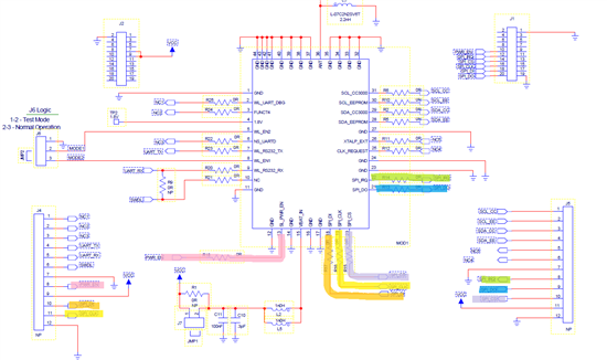
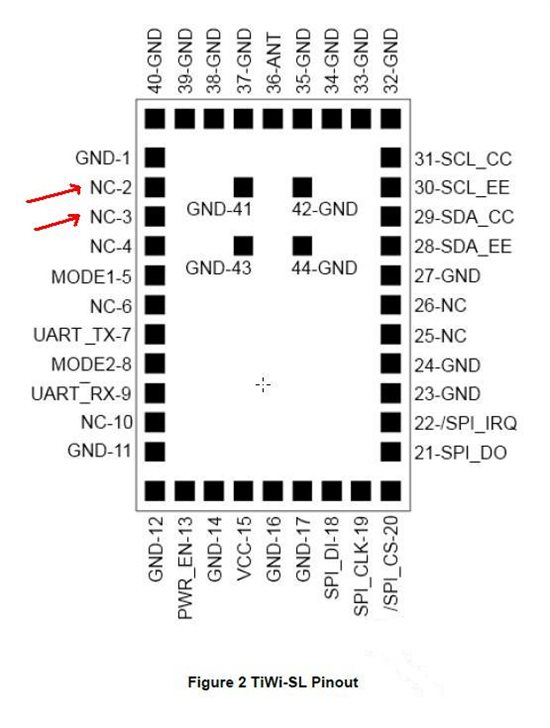
    MOSI (labeled SPI_DI in logic analyzer capture): Direction: MCU->TiWi. Connected to TiWi-SL EM J4.10

    MISO (labeled SPI_DO in logic analyzer capture): Direction: TiWi->MCU. Connected to TiWi-SL EM J5.9

    PWR_EN (labeled PWR_EN in logic analyzer capture): Direction: MCU -> TiWi. Connected to TiWi-SL EM J4.8

    \SPI_IRQ (labeled SPI_IRQ in logic analyzer capture): Direction: TiWi->MCU. Connected to TiWi-SL EM J5.8

    \SPI_CS (Labeled SPI_CS in logic analyzer capture): Direction: MCU->TiWi. Connected to TiWi-SL EM J5.10

    SPI_CLK (Labeled SPI_CLK in logic analyzer capture): Direction: MCU->TiWi. Connected to TiWi-SL EM J4.11 

  • Hi,

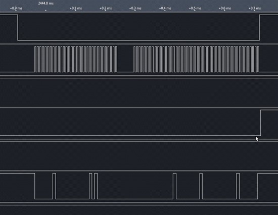
    Can you sample with X-Axis as time? I see a difference between my scope capture to yours but I'm not sure if this is due to different X-Axis.

    As you can see in the following capture, SPI clock looks different, also the MOSI. If the data received by CC3000 is not correct, the command sequence will not continue and the device will not wake up.

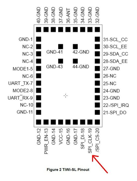
    Regarding your second answer, can you confirm the lines are connected to the module's entries as follows?

    For example, is the SPI clock out from the MCU, is connected to the marked entry in the module?


    Yael

  • Let me address each of your concerns 1 at a time:

    1) Can I sample with X-Axis as time? Yes, future logic analyzer updates will have time instead of sample count.

    2) I see a difference between my scope capture and yours. This is true, but if the CC3000 device is a TRUE SPI Slave, then the only parts that should matter is when the CS goes high and low, and what the signal levels are when the clock is on a falling edge. Just to be sure, I painstakingly bit-banged the SPI bus to try and match yours EXACTLY, and it is still not dropping the IRQ. 

    Here is a diagram of your logic analyzer capture with the SPI bus decoded:

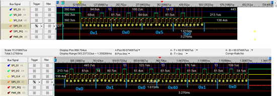
    Here is my capture, with timings, zoomed out:

    Here is also my capture, zoomed in and decoded.

    Do you see any differences now?

    3) Confirm the pinout. All I can really do is trust the LS Research TiWI-SL EM Board schematic:

    Soo....what now?

  • Hi,

    The scope capture looks good, also the pin select.

    I have two more questions: what is the spi clock rate you set and do you have one more module available?

    Yael

  • One more question - do you have only the module (or modules) or do you have our development kit?

    If you have the development kit, I would suggest testing the module functionality with the supplied MCU (MSP430FR5739) which we have demo application with functional SPI driver.

    If this won't work as well, there is something damaged with the module.

    If this works and your setup still doesn't, we will continue with the investigation.

    Yael

  • I have two of the same modules, which are behaving the exact same way.

    Since I am bit-banging the SPI bus at this point, I will have to measure it again to get exact measurements of clock frequency. I have tried with faster (1MHz) and slower clock rates, but you can see relative to other timings that it is very closely matching your clk frequency.

    I have a TI experimenter board on the way, but it will not be shipped until next Monday. We are dropping this device if it is not working by Friday. I will maintain that the host should not matter. I should be able to hook up toggle switches and replicate this problem by hand. If the logic analyzer looks identical to yours, what does it matter what the host is? 

    Also, you claim that it could be damaged, but the IRQ signal is seemingly acting correctly (up until it needs to drop again to indicate a new message is available). Also, the device is writing some data back on the SPI_DO line so it seems alive to me. Is there ANYTHING I can do or check on any pin of this device to determine proper operation? 

  •  

    When you measure the clock, make sure it is under 16MHz, otherwise it won't work.


    You are right, the host should not meter, but the fact is that it is not working with your host and it does with others.

    I don't blame the host itself, but there are differences between each host configuration.

    I'm sure CC3000 module can work with your host, we just recommend to use TI experimenter board as a reference for a working SPI driver.

    My previous claim that the module is damage is canceled, if you have another module that is behaving the same, it indicated it is not the module.

    I am trying my best to help you, I will consult with my colleges and hopefully we will find a solution before Friday.

    Yael

  • You are correct, there is probably a good reason why it would work on a TI experimenter board and not my setup. Whether it be a hardware configuration, socket power, or some other minor detail.

    Thanks for your help, I look forward to hearing your next instructions/suggestions

  • Hi Jonathan,

    1. Please send us a logger file according to these instructions:

    http://processors.wiki.ti.com/index.php/CC3000_Logger

    It will help us understand what is happening from the CC3000 device side.

    2. Please set the SPI clock to 1Mhz. According to your scope shot it looks like ~140Khz.

    3. Please try to start the device with wlan_start(1) instead of wlan_start(0), just to eliminate damaged patches in the EEPROM.

    Yael


  • Hi Jonathan,


    I am using CC3000 + STM32 for my board and i face excactly the sdame problem what is narated in the above thread. i have two WIFI module CC3000 EM and booster board and both behave the same way i some times gets 02 0 08 10 20 40 80 ... for the first write on my MISO line and i dont get the second IRQ from CC3000 after the first write sd host gets stuct on polling the flag and never comes out of it.


    I am running my STM at 1 MHz CPOL = 0, CPHA = 1. i am really stuct with this issues for past 5 days could you please help me in finding the solutiong for this.

  • Hello,

    I have exactly the same problem. I am using a bare CC3000MOD module from TI. I have tried to perform your logging, serial data appears at the correct baud rate at pin 2 (RESERVED_1 on the Reference design schematic). The other reserved pins, including WL-RS232_TX, do not show any serial activity.

    I have tried both wlan_start(1) and wlan_start(0), the module always hangs. The serial dump is the same in both cases. The logic analyser trace closely matches the 'known good' trace on this website. I have tried playing a bit with the timings but it hasn't changed anything.

    How critical is the 50us delay during the first command? At the moment I have a 200us delay, but a 64us one also did not work. I cannot easily make one that is exactly 50us, so I am asking if this can be the problem before I change the code to make it possible. I don't think this is the problem as the MISO response from the device is already wrong before the delay.

    The current clock frequency is 4MHz but I have tried 1MHz, 16MHz and 32KHz (slowest my host will transmit, to rule out signal integrity problems) also.

    If you want a scope capture of all data and power traces I can provide it if needed.

    The response to my init command is the same as the person starting this topic gets: 0x02 0x04 0x08 0x10 ... (A sliding bit pattern)

    Sincerely,
    Bertold Van den Bergh

  • Bertold,

    We make modules based on this chip but we have had several customers now complain of exactly this issue.  Our sample code works on our own microcontroller boards, but of course this is no use to them.

    Did you manage to solve the problem or get any feedback?

    kind regards

    Ian.

  • Hello,

    Yes, I have gotten further with this, but in the end I switched to a USB wifi dongle as this worked quickly and I was running out of time. The solution is also more flexible.

    It seems the CC3000 is very sensitive to rise time of the SPI lines, especially the CS line. Connecting all lines via a 22Ohm resistor made the module responsive. Sadly it still locked up sometimes and I never figures out how to solve that. Make sure you decouple the power supply very well.

    Sincerely,

    Bertold