This thread has been locked.

If you have a related question, please click the "Ask a related question" button in the top right corner. The newly created question will be automatically linked to this question.

SPI timing requirement for CC3000


Hello,

I am working on porting host driver of cc3000, and I have a question about its initialization. I actually have submitted this question to TI FAE, and is awaiting for their response. But I was wondering whether anybody here could help answer it in the mean time so that I can get it around soon.

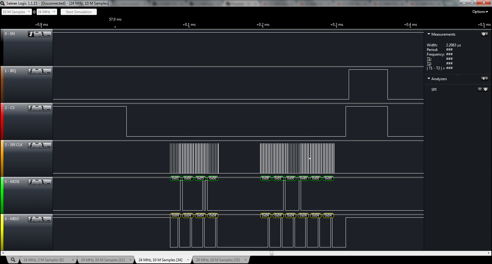
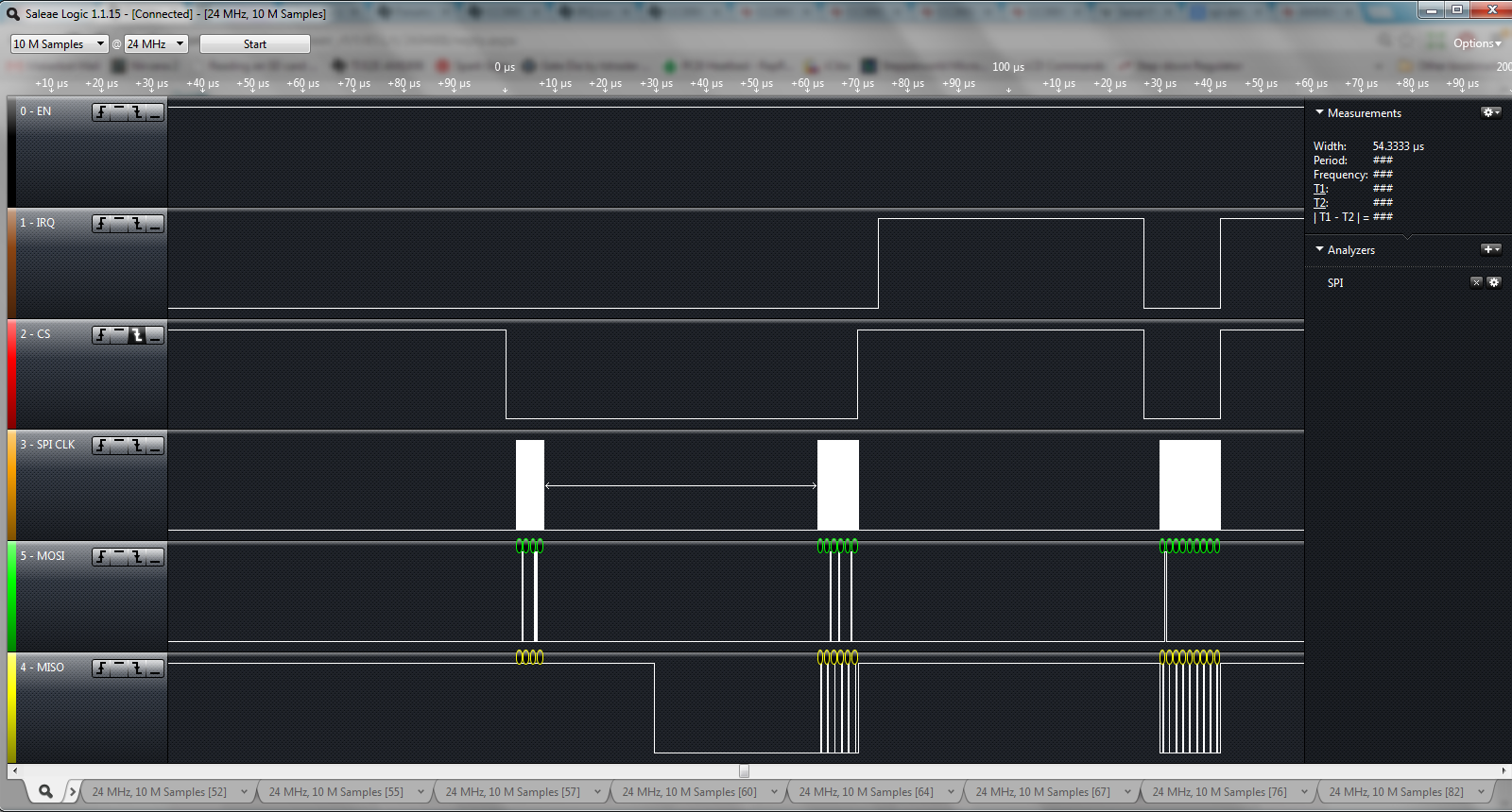
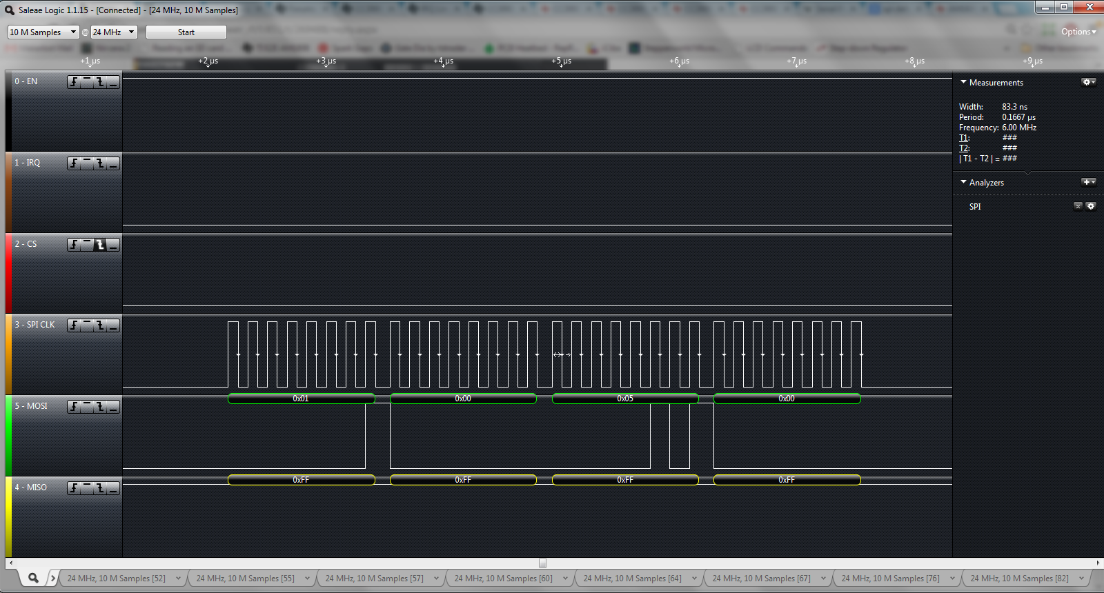
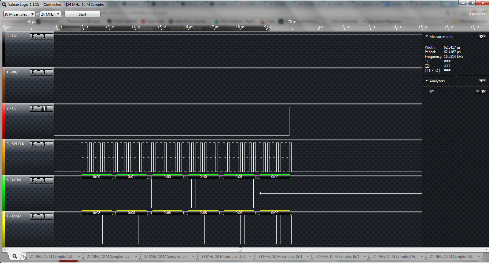
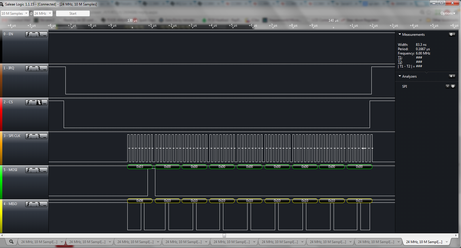
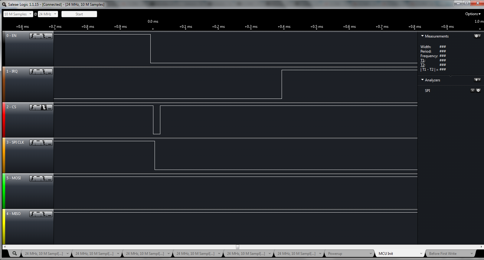
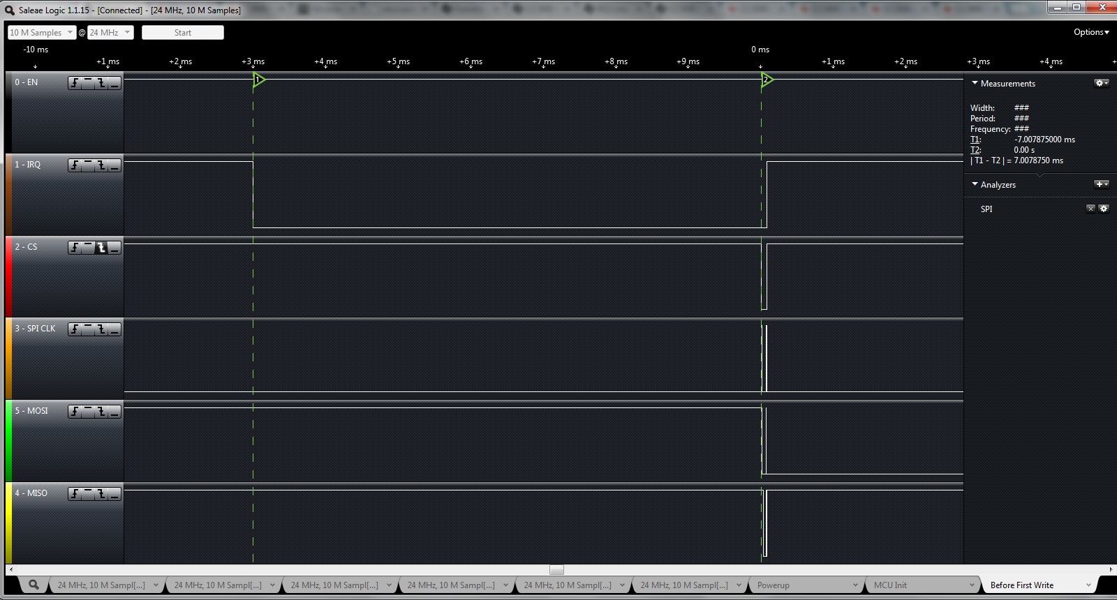
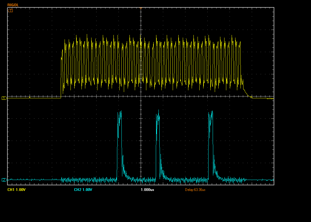
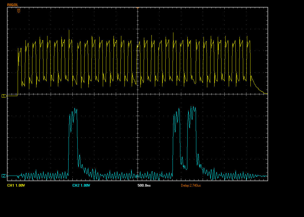
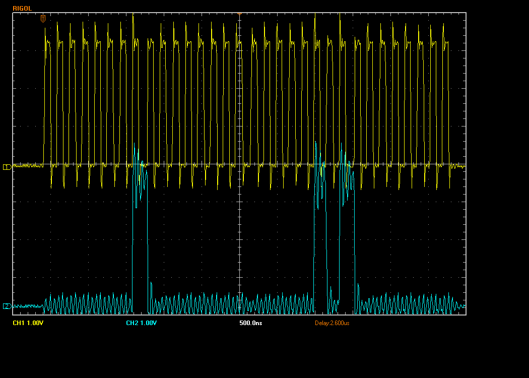
My question is about SPI timing requirement of CC3000. Since the authentic SPI in the MCU is used for other purpose, I am using general purpose IOs to emulate SPI. Then I was getting problem of initialization, especially on the first write, as many others did. The logic of first write to CC3000 is attached for your reference. I was getting data on MISO before the finish of first write. Also all the subsequent data I received on this line later didn't make sense. Thus I were wondering whether it has something to do with SPI timing, as I was not using the authentic interface.

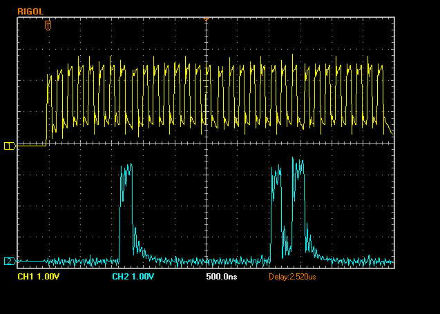
In Table 4 (page 8) of CC3000's datasheet, it requires the pulse width of SPI clock line to range from 25 to 37.5 nanosecond.  For now the shortest pulse we can achieve with GPIO in CCS is only 0.33us, and we could possibly reduce it further by using assemble language in the source codes. But we are afraid we cannot decrease that to an order of 10 to reach 37.5ns target.

Is that true that requirement has to be met? I have seen some people online using SPI clock frequency of 6MHz to communicate with CC3000, and I don't think that clock speed will lead to the pulse width of 37.5ns.

Please advise.

Thanks,

Dawei

  • In order to figure it out, I wired the CC3000 with authentic SPI interface. But this time I was getting very similar result. Could anyone help me?

    My Testing Environment:

    TI MCU + CC3000 + Code Composer v5.4 + Saleae Logic. 3-pin SPI was used and SCS and IRQ were controlled by GPIOs. Clock of SPI is set to 6MHz as I can see apparent signal distortion with higher frequency of SPI CLK. CC3000 is set in function mode (jumper 2-3)

    Since I has been stuck on the first write, I didn't implement the upper layer function of SimpleLink module. Instead, I was doing in a simply way by focusing on the SPI initialization with CC3000 only. Below is my main function.

    int main(void)
    {
    uint32_t payload;
    uint32_t dataIn;

    WIFI_SPI_init();               // init processor, init SPI peripheral

    setOutput(EN, 1);            // enable VBAT_SW_EN
    USTIMER_delay(50000); // in microsecond
    while(getInput(IRQ));       // wait for approximately 53ms before IRQ is driven LOW (Function Mode)
    USTIMER_delay(7000);  // wait for 7ms before CC3000 is ready to accept data

    setOutput(CS, 0);           // assert SPI SCS

    payload = 0x00400100;  // HCI payload to be sent assuming patch is in host, not including 5 bytes of SPI header

    SPIFirstWrite(WRITE, WRITE, payload);     // This should give SIMO: 01 00 05 00 | 00 01 00 40 01 00
    USTIMER_delay(50);                                     // Delay for 50us
    SPIRead(&dataIn);                                        // First Master Read, expect input of 02 00 00 00 05 04 00 40 01 00
    USTIMER_delay(50);
    SPIWrite(WRITE, WRITE, 0x0b400000);    // ask for buffer size of CC3000
    USTIMER_delay(50);
    SPIRead(&dataIn);

    }

    Below are the captured logic waveform.

    1. overall waveform of first write and first read

    2. First 4 bytes of write

    3. Remaining 6 bytes of the first write (54.3us delay after the first 4 bytes)

    4. first read for "command complete"

    I would appreciate it very much if someone could help me out.

    Thanks,

    Dawei

  • Hello Dawei,

    During write operations, the data recieved by the host is irrelevant. See: http://processors.wiki.ti.com/index.php/CC3000_Serial_Port_Interface_(SPI)#First_Host_Write_Operation

    I'm not sure what the reason for the SPI CLK pulse width restrictions are, but I'll find out and let you know soon. In the meanwhile, could you post the subsequent data recieved back from the CC3000?


    Regards,

    Aaron

  • Dawei,

    Read transactions are supposed to be initiated by the CC3000. The IRQ line will drop low indicating when something is ready to be read. I see in your logic that you drive CS low before IRQ goes low.


    Regards,

    Aaron

  • Hi Aaron,

    Thanks for looking at my case. Attached is the complete waveform. You can open it with Saleae Logic after unzipping it.

    Let me know if you have a problem opening it.

    Best,

    Dawei

  • Hi Aaron,

    You mean I should not assert SCS unless IRQ drops?  I will modify the code and let you know how it goes.

    Thanks,

    Dawei

  • Aoran,

    IRQ didn't drop within 4 seconds after the first write. 

    Also the reason I asserted CS before IRQ is in this diagram below. So this is a mistake in the wiki page?

    http://processors.wiki.ti.com/index.php/File:CC3000_Master_SPI_Write_Sequence_After_Power_Up.png

    Best,

    Dawei

  • Hi Aoran,

    I further confirmed that IRQ doesn't drop ~15 seconds after first write. So I believe it would never drop under such situation.

    I have a few more screenshot showing what happens before the first write, which might be of your interest.

    1. Board Power Up. This is the waveform when the board is powered on. It seems there is already 63ms delay before IRQ drops low.

    2. Not util board is powered on, CCS could be run in debug mode. During this step, MCU starts to init; SPI peripheral is also initialized after that. This corresponds to WIFI_SPI_init() above.

    3. Execute the power on sequence of CC3000, referring to page 9 of CC3000 datasheet. Enable VBAT_SW_EN, wait until IRQ goes low. Wait for 7ms more before assert CS and carry out CC3000 init operation, as shown in SPI wiki page.

    The two short pulse on SPI CLK indicates the first 4 bytes and subsequent 6 bytes write, which has already been posted earlier.

    Thanks,

    Dawei

  • Hi Dawei,

    On your last diagram, it looks like you still need to make sure to wait 50us after driving CS low before writing data.


    Regards,

    Aaron

  • In addition to some pre-first-write logic screenshot, here are the real waveform about the first write. I have seen people in this post solving their problem by adding a capacitor on SPI CLK, making me thinking about potential signal integrity problem. The signals were sampled using Rigol DS1052E 50MHz scope.

    1. The first 4 bytes of SPI CLK (upper) and SIMO (lower)

    2. Remaining 6 bytes

    As can be seen the voltage of SPI CLK is lowered than expected for some reason, but it is still higher than VIH of 2V, so I guess it should be fine. There are also some ringing issue on both rising and trailing edge. I can add a RC snubber circuit to mitigate if that's necessary.

  • Hi Aoran,

    I added that delay after asserting CS, but IRQ still failed to drop after first write. By the way, I remove the codes fo ~52ms delay after asserting EN as IRQ was already ready (low) at that time. I also compared by adding the 52ms delay back and it makes no difference to the picture below.

  • Dawei,

    I wouldn't trust the output of that SPI CLK, and it looks like it may trigger more times than intended. Also the level (especially on the first pulse) is too low to be reliable. Is there a way you could get these signals from your micro to come out better?


    Thanks,

    Aaron

  • Aoran,

    This time I am probing the signals right beside the corresponding pins of CC3000, so I believe the waveform below would be very close to what CC3000 picks up. The signals shows less noisy which I guess is because of using two probe grounds this time. (I only grounded one probe on last measurement)

    1. First 4 bytes (updated)

    2. Start of remaining 6 bytes

    Other than resolution limitation in high sample bandwidth of this scope, I think the waveform on SPI clock is acceptable. Even for the first pulse, VIH is larger than 2V so there shouldn't be trigger problem.

    While you are looking at reasons other than CLK votage, I will be working on ways of increasing the CLK voltage.

    Thanks,

    Dawei

  • Hi Aoran,

    There was AC impedance for SPI CLK. After taking them out, the SPI clock could reach 3.3V. Here is how they look like for the first 4 bytes (probing beside pins of CC3000).

    I believe the waveform looks okay now.

    Then I ran the codes in code composer studio with 50us delay after CS. However IRQ didn't drop as well this time.

    I have attached the entire data session for your reference.

    http://e2e.ti.com/cfs-file.ashx/__key/communityserver-discussions-components-files/851/3404.1439.zip

    Thanks,

    Dawei

  • Hi Aoran,

    Now that voltage level on SPI clk has been excluded, let's take a step back and see what could be the reason.

    I am still concerned about timing, including SPI timing and power-on sequence.

    None of the waveforms above hits the 37.5ns maximal high pulse width, as specified in the CC3000 datasheet. But the datasheet also states that 0~16MHz clock frequency is acceptable. I don't feel it is reasonable. For example, my MCU supports SPI clock up to 16MHz, however, it seems there is no way adjust the duty cycle. As a result of 50% duty cycle by default, the only way to reach that 37.5ns is to increase clock speed to 26MHz. But that's overkill for SPI.

    Speaking of power-on sequence, do you think the process of MCU initialization after board power up, including setting GPIOs for EN and CS, would affect init of CC3000? From most posts I have seen online, they are debugging the init in firmware, not in CCS, where the init of CC3000 could be executed immediately after power up of the board. As you can see in the screenshot of board power up, the IRQ has already been dropped, indicating the module is ready to receive data. However we didn't write to it until we started to run CCS a long while later. The states of CS and EN were also toggled half way in the middle when their GPIOs were configured, though they returned very quickly while IRQ remained low. 

    How do you think about it?

    Meanwhile I am going to try wiring the SPI to one CC3000 evaluation board from LS Research, and see what happens.

    Thanks,

    Dawei

  • It is time to conclude and close this topic. I finally found the problem, which has something to do with the CS glitch during MCU init ,as speculated in my previous post.

    This issue should only occur to those who use CCS to debug because the power on sequence of CC3000 now breaks into three steps, board power on, start CCS software, start MCU and CC3000 init. The problem lies in the first and last step. After board power up, IRQ should go low already, indicating it is ready to receive data. Meanwhile CS pin goes high by default. Then during the 3rd step MCU sets the direction of GPIO for CS and EN as output, and then write value 1 to them. However, the output of GPIO is low by default after direction being set, and this will create a very short high-low-high glitch on CS line. Refer to one of the pictures above showing the process WIFI_SPI_init().

    I believe it is this CS glitch that interrupt the internal state of CC3000 so that the first write never succeeds. The solution is to set init value 1 of CS before setting direction of this GPIO. That will make all the difference.

    I have test both real and bit-bang SPI schemes, and I was getting correct waveform now on both from CC3000 during the initialization, exactly the same as what the CC3000 SPI wiki page shows.