This thread has been locked.

If you have a related question, please click the "Ask a related question" button in the top right corner. The newly created question will be automatically linked to this question.

Antenna Matching

Other Parts Discussed in Thread: WL1801MOD, WL1835MODCOM8B

Hello,

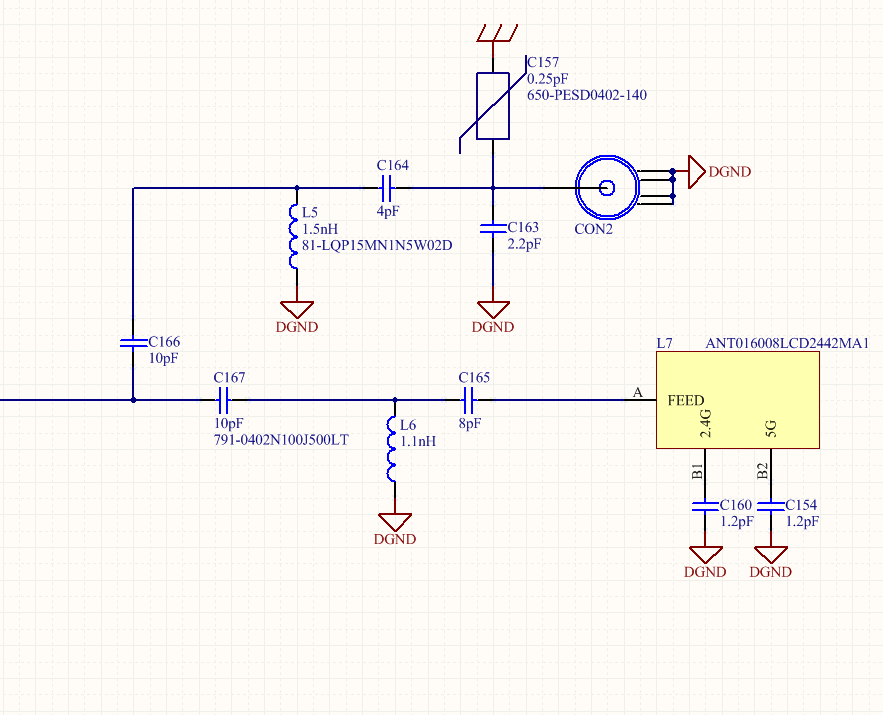
I am more or less new to this. I want to insert two antennas to TI's WL1801MOD. The first antenna is a chip antenna ANT016008LCD2442MA1 and the other one an external antenna connected to a 50 ohm cable through a connector. What should I have to consider in this design. Just design 50 ohm impedance line from the chip to the antennas is enough or I have also design a matching network. Does the length of the line plays any particular role when designing a matching network. I'll also have to meet the FCC requirements for WLAN. I am asking this question because in evaluation boards they  use different matching networks than the one that TDK proposes in the datasheet http://product.tdk.com/en/catalog/datasheets/rf_ant_ant016008lcd2442ma1_en.pdf. The external antenna is going to have a standard impedance of 50 ohms. Can anyone help me with this? Thanks.

  • Hi,

    I am checking this with the RF designer - and I will let you know once I have an answer.

    Regards,
    Gigi Joseph.

  • Thanks. Just to specify things I dont want to use both antennas at the same time. One of them is going to be used each time. So the correct schematic can be seen in the following picture. We want each time to discard ether C166 or C167 so the two antennas are going to be totally isolated. So which is the best solution for me. I have to follow what the manufacturer of the chip antenna suggests in the datasheet or the one that is used in evaluation boards. Do I have also try to include a matching network for the external antenna or a 50 ohm line is ok? By the way WL1835MODCOM8B WLAN MIMO and Bluetooth® Module Evaluation Board for TI Sitara™ Platform and BeagleBone-WL1835MOD-RevA1 use the same configuration for external and internal antenna but different matching networks.

  • Hi,

    Please note that to reuse our certification is only possible with chip antenna so second antenna will require Permissive change 2 that is almost full certification.

    The chip antenna must be less or equal gain as our TDK one.


    As long as the trace is kept 50R there is no need for matching of the swivel antenna à of course if the line will be too long there will be a degradation in performance because of insertion loss.

    For the chip antenna there is a need to place pi style matching near it as described in our DS.


    Regards,
    Gigi Joseph.

  • Hi,

    Thank you very much for the feedback. I am going to use the same chip antenna in my design. Also I am going to use one antenna (chip or external) each time as I wrote before by discarding either c166 or c167. However in your evaluation boards you are using different configuration for this chip antenna matching network. Which of them Am I supposed to use in my design? You can take a look for this different matching networks in the following links

    http://www.ti.com/lit/ug/swru359c/swru359c.pdf

    http://www.ti.com/lit/ds/symlink/wl1801mod.pdf

    http://boardzoo.com/index.php/catalog/product/view/id/146/category/8

    Thanks

  • Hi,

    The layout is different between the 2 boards and each one has it’s optimized network – to use the same FCC ID of the COM8 there is a need to use similar matching.

    Regards,
    Gigi Joseph.