


Here is a schematic from datasheet of CC3200
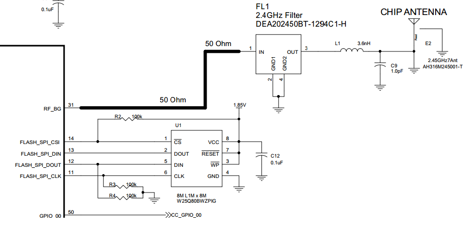
Here is datasheet of the FL1 filter on http://product.tdk.com/en/catalog/datasheets/rf_bpf_dea202450bt-1294c1-h_en.pdf which I can't find it on stock anywhere. Instead, I am planning to use another RF filter from Johanson technology http://www.farnell.com/datasheets/87155.pdf Do you have any application note that explains how to replace the filter and/or how to decide what values to choose for L1 and C9 pair for a different PCB stack?
I am not much familiar with RF filters, what impedance should be measured on pin 3 of the filter? I will have a 50 ohm antenna at the end of the microstrip, can I select any L1 and C9 values that matches the impedance or what do I need to consider to selecting the L-C values?
