This thread has been locked.

If you have a related question, please click the "Ask a related question" button in the top right corner. The newly created question will be automatically linked to this question.

I2C issue (CC3200)

Other Parts Discussed in Thread: CC3200MOD, CC3200

Hello Everybody,

I have CC3200mod (master) with connected accelerometer (slave) on pins 05 (CLK, GPIO14) and 06 (DATA, GPIO15).

I have configured I2C as follows:

MAP_PRCMPeripheralClkEnable(PRCM_I2CA0, PRCM_RUN_MODE_CLK);

MAP_PinTypeI2C(PIN_05, PIN_MODE_5);

MAP_PinTypeI2C(PIN_06, PIN_MODE_5);

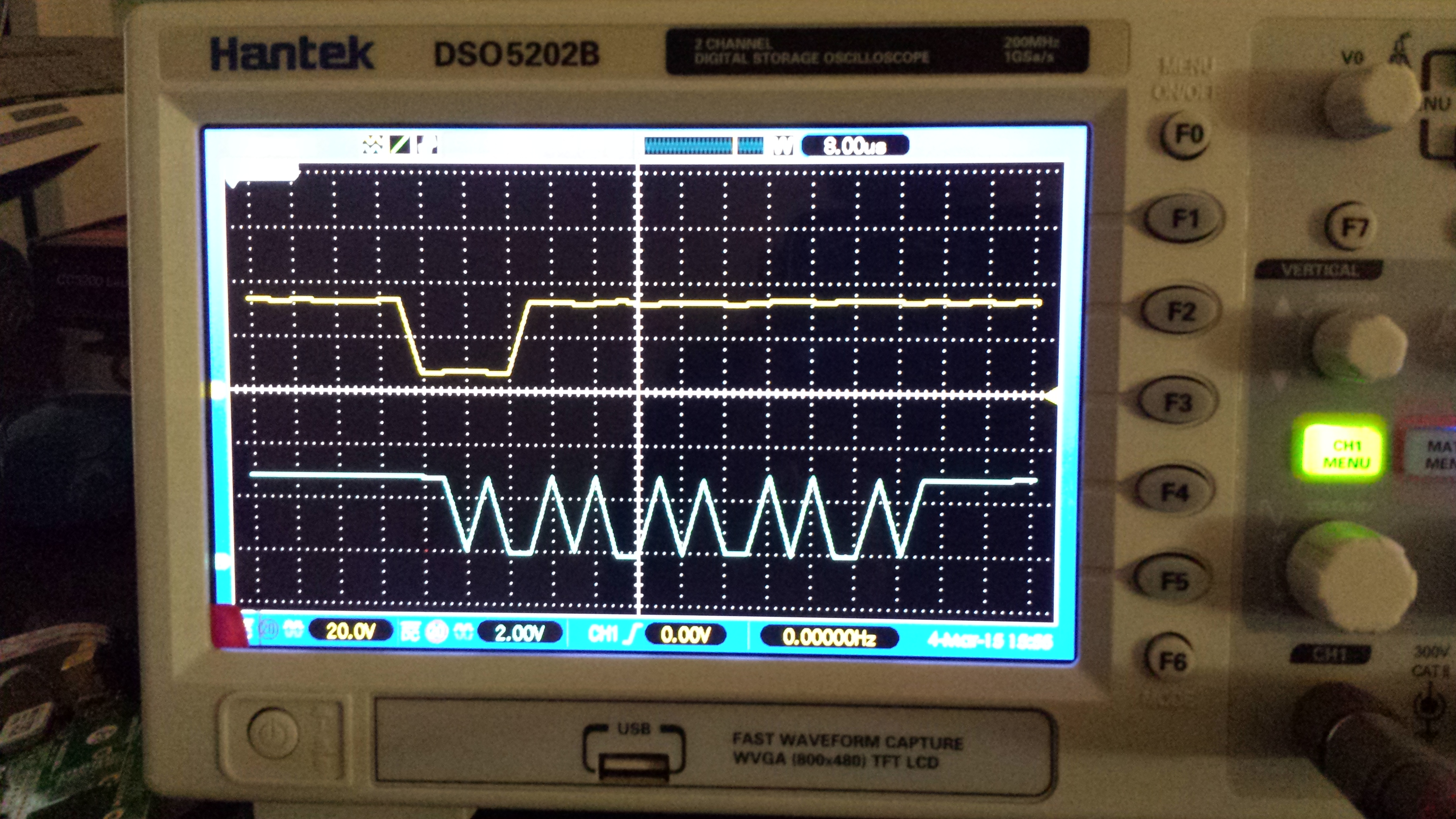
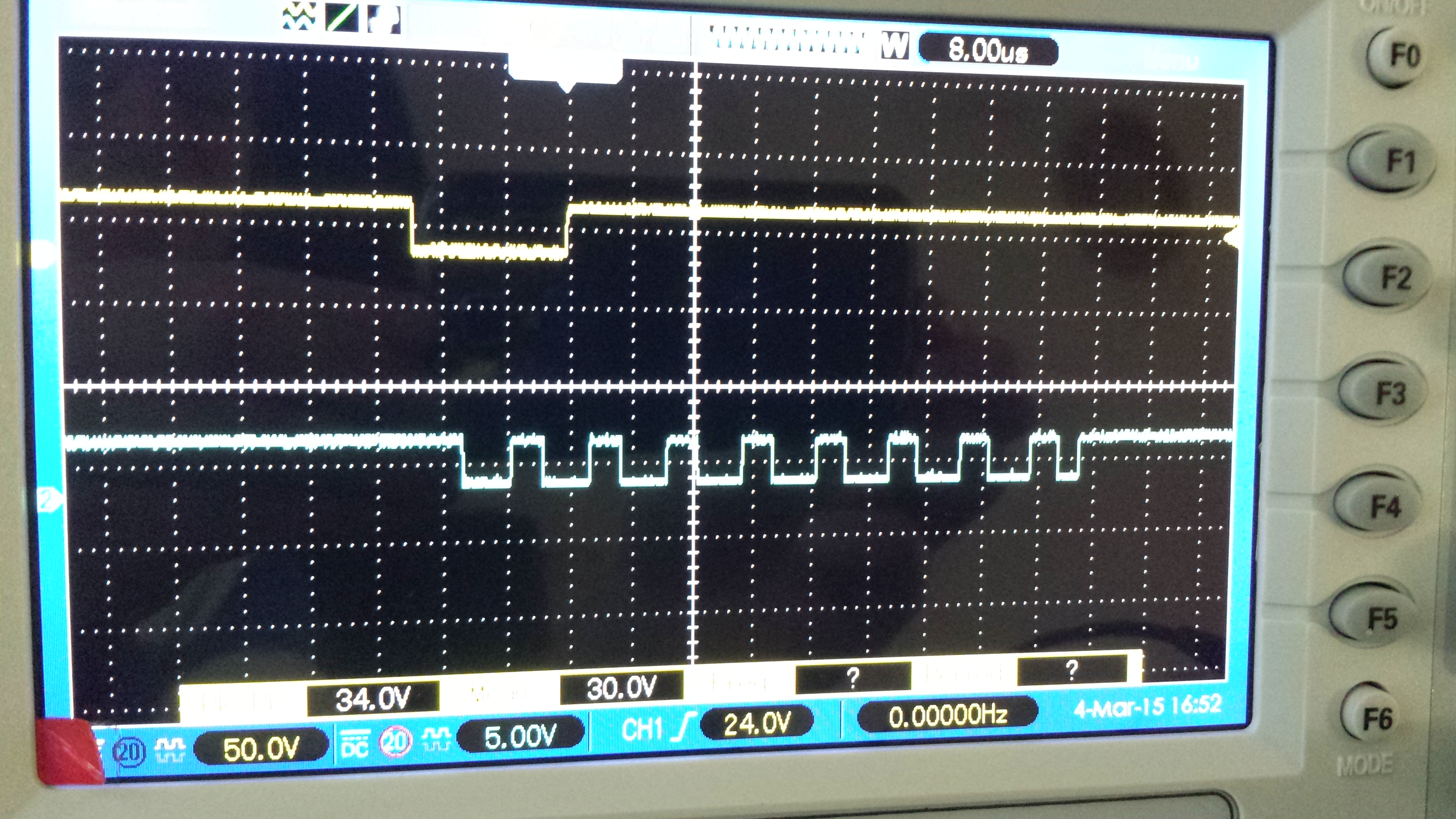
The problem is when i tried to read a DATA there is no clock, DATA changes from high to low and nothing happens (like freezing).

Please help me to solve the problem.

Thank you.

  • Do you have proper pullup resistors on your I2C lines?
  • Hello Steve,

    Resistors on pull up are 1K.

    The picture of scope attached (when we send "readreg" command to accelerometer using TI-RTOS).

    Top (yellow) signal is DATA and lower is CLOCK (blue).

    What do you think about it?

  • Those edges don't look right at all.  It looks like you may have a ton of capacitance on your lines.  Do you have a lot of devices connected to the I2C port?  IME 1K is probably too low for a pullup value, but your edges clearly aren't moving fast enough.  I'd try to figure out why your lines have so much capacitance before I do anything else.

    Are you trying to run 100KHz or 400KHz?  I recommend starting with 100KHz to keep it simpler.

  • There is only a one device (accelerometer) connected on address 0x1C.

    I tried 100KHz.

    I do not see the address is transfered. 

    One more picture attached: 

  • Hi Gleb,

    Did you try running the i2c_demo example code?
    Besides the pin muxing which looks ok, did you remember to initialize the I2C, by calling to I2C_IF_Open(I2C_MASTER_MODE_FST) ?
    Can you please provide a code snippet of your entire I2C handling, including init, read\write?

    Thanks,
    Alon
  • Hi Alon,

    1. Yes we tried i2c_demo example code, but there were no clock signal on I2C bus.
    2. We are using TI-RTOS (according to example i2ctmp006_CC3200) and here is our code:

    uint8_t txBuffer[1];
    uint8_t rxBuffer[2];
    I2C_Handle i2c;
    I2C_Params i2cParams;
    I2C_Transaction i2cTransaction;

    / Create I2C for usage /
    I2C_Params_init(&i2cParams);
    i2cParams.bitRate = I2C_100kHz;
    i2c = I2C_open(Board_I2C0, &i2cParams);
    if (i2c == NULL) {
    System_abort("Error Initializing I2C\n");
    }
    else {
    System_printf("I2C Initialized!\n");
    }

    txBuffer[0] = 0x0d; // Who i am register of accelerometer
    i2cTransaction.slaveAddress = 0x1c; // Slave address of accelerometer
    i2cTransaction.writeBuf = txBuffer;
    i2cTransaction.writeCount = 1;
    i2cTransaction.readBuf = rxBuffer;
    i2cTransaction.readCount = 1;

    if (I2C_transfer(i2c, &i2cTransaction)) {
    System_printf("Value %d\n", rxBuffer[0]);
    }

    Pinmux file:
    MAP_PRCMPeripheralClkEnable(PRCM_I2CA0, PRCM_RUN_MODE_CLK);
    MAP_PinTypeI2C(PIN_05, PIN_MODE_5);
    MAP_PinTypeI2C(PIN_06, PIN_MODE_5);
  • I've got this working on my cc3200 + ti-rtos:

    pinmux.c

    ...


    MAP_PRCMPeripheralClkEnable(PRCM_I2CA0, PRCM_RUN_MODE_CLK);

    /*I2C*/ // // Configure PIN_01 for I2C0 I2C_SCL // MAP_PinTypeI2C(PIN_01, PIN_MODE_1); // // Configure PIN_02 for I2C0 I2C_SDA // MAP_PinTypeI2C(PIN_02, PIN_MODE_1);

    i2c.c

    ...

    /*
     *  ======== I2C_init ========
     */
    void I2C_Helper_init(unsigned int indexI2C, float freq )
    {
    	    uint8_t newmode;
    	    uint8_t oldmode;
    
    	    i2cTransaction.slaveAddress = 0x40; //Slave address
    
    	    /* Create I2C for usage */
    	    I2C_Params_init(&i2cParams);
    	    i2cParams.bitRate = I2C_400kHz;
    	    i2c = I2C_open(indexI2C, &i2cParams);
    	    if (i2c == NULL) {
    	        System_abort("Error Initializing I2C\n");
    	    }
    	    else {
    	         System_printf("I2C Initialized!\n");
    	         System_flush();
    	    }
    }


    /*
     *  ======== I2C_set_Data ========
     */
    
    void I2C_set_Data(uint8_t channel, uint16_t value)
    {
    	txBuffer[0] = (0x6+4*channel); //LED0_ON_L at port number
    	txBuffer[1] = 0x0; //on
    	txBuffer[2] = txBuffer[1]>>8; //on
    	txBuffer[3] = value; //off
    	txBuffer[4] = value>>8;//off
    
    }


    /*
     *  ======== I2C_send_and_receive_Data ========
     */
    void I2C_transfer_Data(void)
    {
    	i2cTransaction.writeBuf = txBuffer;
    	i2cTransaction.writeCount = 5;
    	i2cTransaction.readBuf = rxBuffer;
    	i2cTransaction.readCount = 0;
    
    	 if (I2C_transfer(i2c, &i2cTransaction)) {
    		    	
    		}
    		else {
    			  System_printf("I2C Bus fault\n");
    			  System_flush();
    			  }
    
    	/* Deinitialized I2C */
    //	I2C_close(i2c);
    //	System_printf("I2C closed!\n");
    //	System_flush();
    
    }

    Don't forget to activate the i2c drivers in your ti-rtos config.

    Maybe it helps

  • Hi Gleb,

    Pin 1 (GPIO 10) and Pin 2 (GPIO 11) are configured as I2C by CC3200 boot loader.
    To use I2C on different pins, you will need to configure these pins 1 and 2 in mode other than I2C.

    Regards,
    Ankur