This thread has been locked.

If you have a related question, please click the "Ask a related question" button in the top right corner. The newly created question will be automatically linked to this question.

New custom CC3200 board: can't debug or flashing using CC3200 LAUNCHPAD's built-in tools

Other Parts Discussed in Thread: CC3200, UNIFLASH

Hello,

I have designed a new custom board based on "Figure 6-1. Schematics for CC3200 Wide-Voltage Mode Application" in the cc3200 datasheet. I have used CC3200 LAUNCHPAD's built-in tools for debugging and download flash to the new board but all were failed:

1. For debugging:

 -  I removed all jumpers J8, J9, J10, J11 of LAUNCHPAD board, connected TCK, TMS, TDI, TDO to my board and tried debug using CCSV6.1.1. 

 - Application downloading to the chip was done without any error but the program pointer didn't get into main(). (Please see the attached figure)


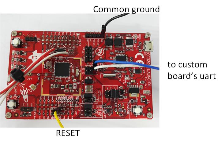
2. For flash downloading using UniFlash:

 - I have removed all Jumpers from J6, J7 headers of LAUNCHPAD board, connected Pin3 of J6, J7 header to my UART0_RX, UART0_TX pins.

 - Pulled SOP2 or my board to HIGH level, reset the board, used UniFlash to do format and download application file. However, It always shown "ERROR: ---reading ACK signal failed---". It is likely that the board couldn't get into "application download" mode

3. I have tried to connect the LP_RESET_OUT on LAUNCHPAD board to RESET pin on my board but there was no luck.

What wrong did I do? Did I skip any step or connection?

  • Can you go through the below link to see if anything is missing from your design.
    processors.wiki.ti.com/.../CC31xx_&_CC32xx_HW_Debugging_AppNote
  • Hello,

    Thank you for your advice.

    So far I have solved the first problem, it means that I can debug the board using CCS + Launchpad's FTDI. That's was my mistake, in this customized board the chip is CC3200R1M1 with only 128KB SRAM, after modifying the system memory map in cc3200v1p32.cmd file, debugging is fine.

    However, the second problem still exists, I couldn't use Lauchpad's FTDI uart to download flash to my customized board by UniFlash. So could you please confirm whether this method is possible or not?

    Again, I post the photo showing how I connected my board to Lauchpad's FTDI.

    One more note, if I put a pre-flashed memory into my board, it works, the UART0 connection also works.

    Thanh you.

  • Check the state of the SOP signals on your board. For flashing, the SOP[2:0] should be [100]. Other than this, your configuration should work.
  • HI, 

    We are facing an issue regarding flashing of the external Flash on our custom board. 

     This is how we have connected the launchpad to our custom board.

     We are using the CC3200R1M1 MCU on the custom board.

     1) First of all we have rechecked flashing the external flash on the Launchpad and it was successful.

    2) We have connected JP6(3) and JP7(3) to the respective UART pins of the custom board .i.e. GPIO_01 and GPIO_02. Also SOP2 was pulled high via voltage divider R1 = 270ohm and R2 = 2.7kohm.

    SOP0   and SOP1 was pulled low via 100kohm resistors.

    GND was connected common to the launchpad.

     Keeping the flashing of the flash aside for a moment, we noticed that we could not even communicate with our MCU placed on the custom board .i.e, to get the boot loader version and chipset version.

     All this process is done using CCS Uniflash tool.

     Please confirm and let us know if any there is anything we are doing wrong or missing.

    Thanks,

    Utpal

  • Hi All,

    Please help.