This thread has been locked.

If you have a related question, please click the "Ask a related question" button in the top right corner. The newly created question will be automatically linked to this question.

CC3200 SPI Mode 0 problem

Other Parts Discussed in Thread: CC3200, LM3S8962

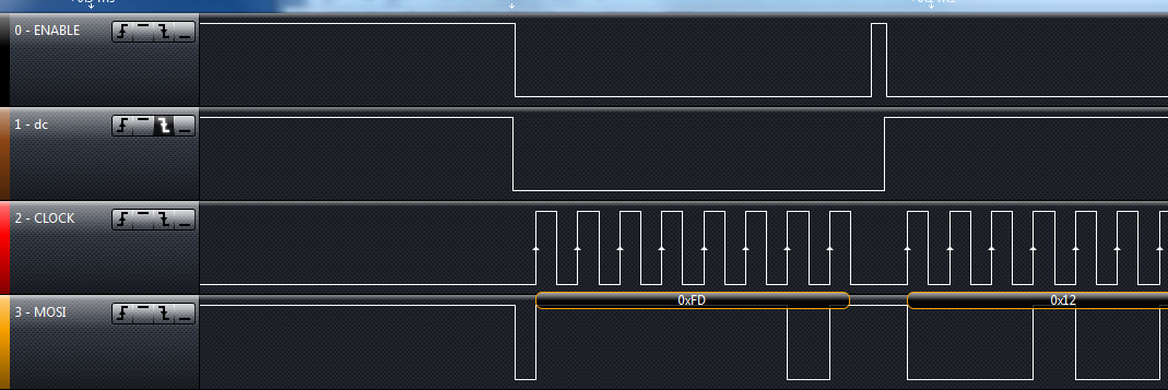
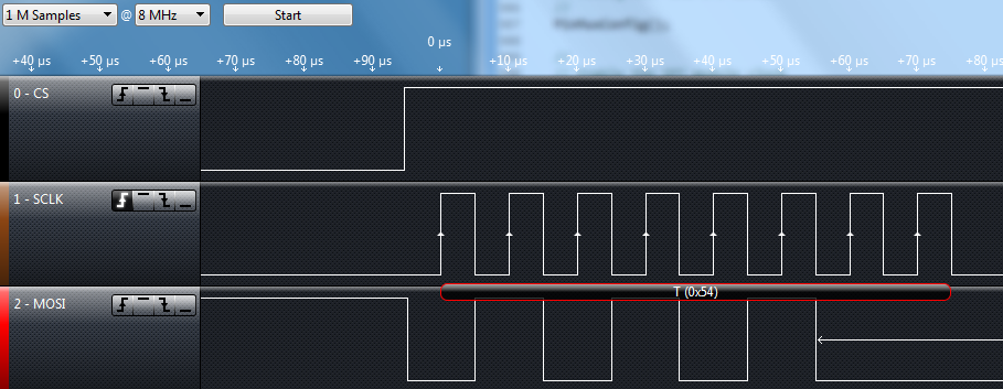
I'm interfacing to an OLED using the CC3200 SPI port. The CC3200 seems to output incorrect signals in Modes 0 and 2. The data (MOSI) should be asserted when the SPIEN goes active, but instead it is asserted on the first clock edge, which is also when the data is sampled when PHA=0. Modes 1 and 3 work correctly because the MOSI data is asserted on the first clock edge and sampled on the second as expected when PHA=1. I've verified this with a logic analyzer on 2 different CC3200 LauchPads.

You can see in the screenshot that the MSB is not asserted when ENABLE goes low, but when CLOCK goes high. This is when data should be sampled in Mode 0. I'm using the following command to configure the SPI:

SPIConfigSetExpClk(GSPI_BASE,PRCMPeripheralClockGet(PRCM_GSPI),
SPI_IF_BIT_RATE,SPI_MODE_MASTER,SPI_SUB_MODE_0,
(SPI_HW_CTRL_CS |
SPI_4PIN_MODE |
SPI_TURBO_OFF |
SPI_CS_ACTIVELOW |
SPI_WL_8));

I've successfully used Mode 0 with this OLED using a Tiva LaunchPad and a Stellaris LM3S8962 Evaluation Kit. Fortunately, Mode 3 works with the CC3200 LaunchPad. This Mode 0 problem seems like a hardware bug to me. Has this been seen before?

  • HI Lance,

    Please check you logic analyzer resolution.. this is the first thing I can think of which may be producing what you see. Try reducing the clock speed and compare also.

    Thanks,
    Aaron
  • Hi Aaron,

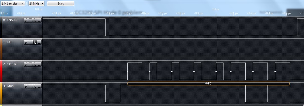
    I get the same results using 24 MHz or 16 MHz. This is as slow as I can go when I use an SPI clock of 8 MHz. Here is the result on the Tiva 4C123 launchpad using Mode 0 (which WORKS on the same OLED display):

    ROM_SSIConfigSetExpClk(SSI0_BASE, SysCtlClockGet(), SSI_FRF_MOTO_MODE_0,
    SSI_MODE_MASTER, 8000000, 8);

    Note where the MOSI data changes prior to the first rising clock edge and compare it with the CC3200 spi below (and above).

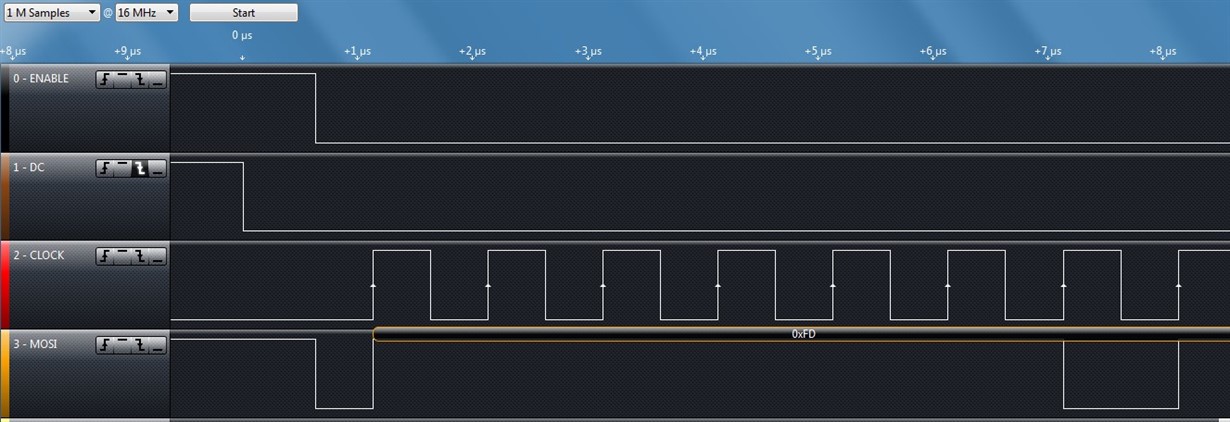
    With the CC3200 launchpad, the waveform looks like:

    Here the SPI clock is 1 MHz and I slowed the logic analyzer clock to 16 MHz. Notice that there is basically no setup time before the rising clock edge. I assume that this is why this mode will not work with the OLED as it should. The logic analyzer correctly decoded the data as 0xFD, but the OLED apparently needs more setup time.

    According to the data sheet, this is not what Mode 0 waveforms should look like! I still think it's a hardware issue / flaw with the CC3200 launchpad SPI peripheral.

    SPIConfigSetExpClk(GSPI_BASE,PRCMPeripheralClockGet(PRCM_GSPI),
    SPI_IF_BIT_RATE,SPI_MODE_MASTER,SPI_SUB_MODE_0,
    (SPI_HW_CTRL_CS |
    SPI_4PIN_MODE |
    SPI_TURBO_OFF |
    SPI_CS_ACTIVELOW |
    SPI_WL_8));

    Thanks,

    Lance

  • Hi Aaron,

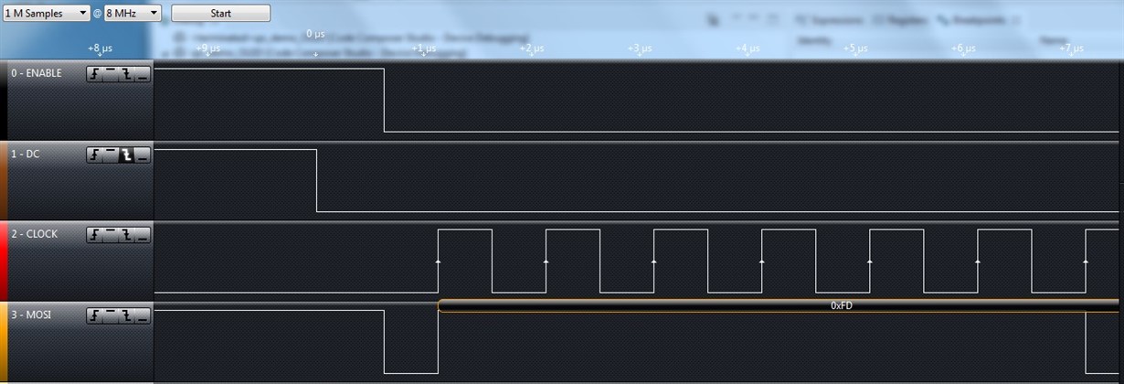
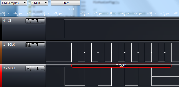
    Here is one more screen-shot with the logic analyzer clock at 8 MHz. The results are the same - basically no setup time on the MOSI data before the first rising edge. I don't think it is a problem with the logic analyzer. I think the CC3200 spi is violating the timing specs. I've gotten the same results with the CC3200 LauchPad with the logic analyzer clock at 24 MHz, 16 MHz, and 8 MHz. As mentioned above, the results show the difference between the CC3200 and the Tiva 4C123 Launchpad.

    Thanks,

    Lance

  • HI Lance,

    Have you taken a look at the SPI_demo example in the SDK and compared its waveform to your's for mode 0?

    -Aaron
  • Hi Aaron,

    Here are the waveforms from the SPI demo example:

    As you can see, it works as expected. The data changes on the falling SCLK edge and is sampled on the rising edge. This is the way Mode 0 should work. 

    I compared this with my code and by adding the line to enable the FIFO after the SPIEnable line (shown below), the timing of the SPI_demo changes to the faulty timing I observed. 

    // Enable SPI for communication
    //
    MAP_SPIEnable(GSPI_BASE);
    SPIFIFOEnable(GSPI_BASE, SPI_TX_FIFO || SPI_RX_FIFO);    // I added this line and it broke SPI Mode 0 timing

    By just adding this one line, the timing changes to:

    Notice that now the data changes are taking place on the rising edge instead of the falling edge, which is incorrect. I don't know why the SPIFIFOEnable command should cause the timing to change like this. I confirmed that taking that line out of my code fixes the timing of my program. I'll have to see if the OLED interface works without the FIFO enabled. Anyway, it seems now like the bug involves the SPIFIFOEnable API.

    Thanks,

    Lance

  • Hi Lance,

    Try enabling the FIFO before the SPI module

    -Aaron
  • Hi Aaron,

    I changed the initialization code to enable the FIFO before configuring the SPI module, as follows:

    SPIReset(GSPI_BASE);
    SPIFIFOEnable(GSPI_BASE, SPI_TX_FIFO || SPI_RX_FIFO);

    //
    // Configure SPI interface
    //
    SPIConfigSetExpClk(GSPI_BASE,PRCMPeripheralClockGet(PRCM_GSPI),
    SPI_IF_BIT_RATE,SPI_MODE_MASTER,SPI_SUB_MODE_0,
    (SPI_HW_CTRL_CS |
    SPI_4PIN_MODE |
    SPI_TURBO_OFF |
    SPI_CS_ACTIVELOW |
    SPI_WL_8));

    //
    // Enable SPI for communication
    //
    SPIEnable(GSPI_BASE);

    This fixed the problem. 

    Thanks,

    Lance