This thread has been locked.
If you have a related question, please click the "Ask a related question" button in the top right corner. The newly created question will be automatically linked to this question.
Dear TI engineers:
I connected CC3200 with MPU6050 with I2C. MPU6050 is attached with another slave device ak8975. ak8975 could be selected as slave by enable the bypass register in MPU6050.
The problem i encountered is that:
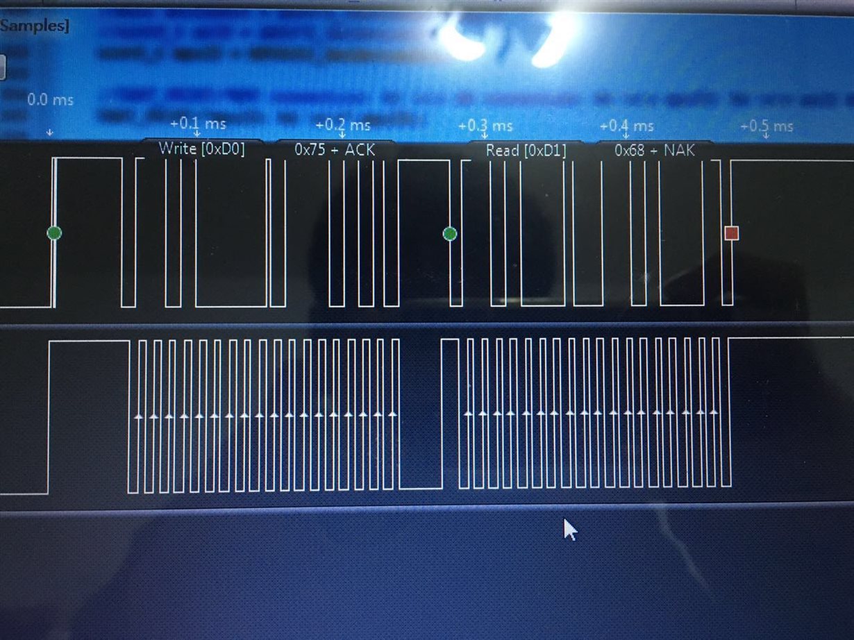
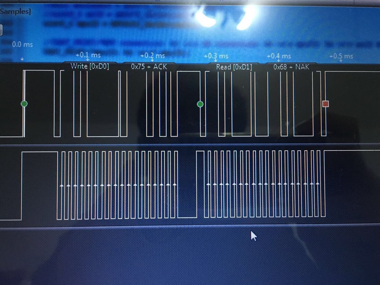
i once successfully connect to MPU6050, as shown in the following graph: (MPU6050 slave address is 0x68, WHO_AM_I register address is 0x75
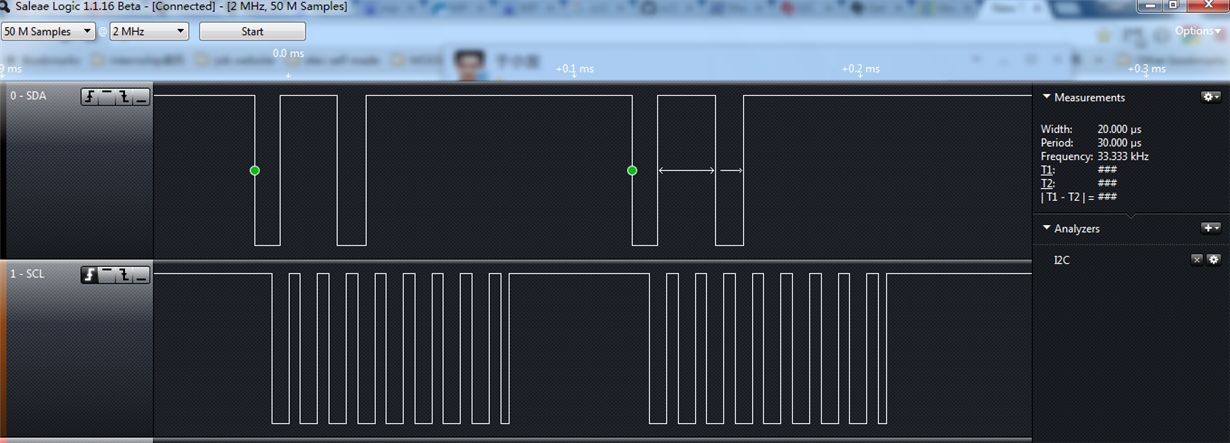
However, later, i dont know what i had done, the communication didnt work anymore. And the error type is I2C_MASTER_ERR_ARB_LOST. the wrong communication is shown below:
there are 2 things i could remember that i did might cause this problem:
1. i tried change the PIN mode configuration from PIN_MODE_5 to PIN_MODE_1, because in the "i2c demo" it used PIN_MODE_1 instead of PIN_MODE_5 which is generated by pinmux tool.
// Configure PIN_03 for I2C0 I2C_SCL
PinTypeI2C(PIN_03, PIN_MODE_5);
// Configure PIN_04 for I2C0 I2C_SDA
PinTypeI2C(PIN_04, PIN_MODE_5);
After i realized that PIN_MODE_1 doesnt work, i changed it back to PIN_MODE_5 immediately.
2. i tried connect the AK8975 by enable the bypass of MPU6050.
I really could not find the cause of problem and solution to it. how does problem related to arbitration lost??
Following are my initialization codes:
void MPU6050_I2C_Init(void){
// Configure PIN_03 for I2C0 I2C_SCL
PinTypeI2C(PIN_03, PIN_MODE_5);
// Configure PIN_04 for I2C0 I2C_SDA
PinTypeI2C(PIN_04, PIN_MODE_5);
MAP_PRCMPeripheralClkEnable(PRCM_I2CA0, PRCM_RUN_MODE_CLK);
MAP_PRCMPeripheralReset(PRCM_I2CA0);
MAP_I2CMasterInitExpClk(I2CA0_BASE,SYS_CLK,false); // set up the transfer to standard mode
MAP_I2CMasterEnable(I2CA0_BASE);
MAP_I2CMasterIntEnable(I2CA0_BASE);
}
Thanks
Dear TI engineers:
I connected CC3200 with MPU6050 with I2C. MPU6050 is attached with another slave device ak8975. ak8975 could be selected as slave by enable the bypass register in MPU6050.
The problem i encountered is that:
i once successfully connect to MPU6050, as shown in the following graph: (MPU6050 slave address is 0x68, WHO_AM_I register address is 0x75
However, later, i dont know what i had done, the communication didnt work anymore. And the error type is I2C_MASTER_ERR_ARB_LOST. the wrong communication is shown below:
there are 2 things i could remember that i did might cause this problem:
1. i tried change the PIN mode configuration from PIN_MODE_5 to PIN_MODE_1, because in the "i2c demo" it used PIN_MODE_1 instead of PIN_MODE_5 which is generated by pinmux tool.
// Configure PIN_03 for I2C0 I2C_SCL
PinTypeI2C(PIN_03, PIN_MODE_5);
// Configure PIN_04 for I2C0 I2C_SDA
PinTypeI2C(PIN_04, PIN_MODE_5);
After i realized that PIN_MODE_1 doesnt work, i changed it back to PIN_MODE_5 immediately.
2. i tried connect the AK8975 by enable the bypass of MPU6050.
I really could not find the cause of problem and solution to it. how does problem related to arbitration lost??
Following are my initialization codes:
void MPU6050_I2C_Init(void){
// Configure PIN_03 for I2C0 I2C_SCL
PinTypeI2C(PIN_03, PIN_MODE_5);
// Configure PIN_04 for I2C0 I2C_SDA
PinTypeI2C(PIN_04, PIN_MODE_5);
MAP_PRCMPeripheralClkEnable(PRCM_I2CA0, PRCM_RUN_MODE_CLK);
MAP_PRCMPeripheralReset(PRCM_I2CA0);
MAP_I2CMasterInitExpClk(I2CA0_BASE,SYS_CLK,false); // set up the transfer to standard mode
MAP_I2CMasterEnable(I2CA0_BASE);
MAP_I2CMasterIntEnable(I2CA0_BASE);
}
Jain,
By default, I2C in muxed onto pin 01 and 02. Since this allocation is not used in your application, we recommend that these pins are configured to GPIO (or any other functional mode) before configuring the I2C controller.
PinModeSet(PIN_01,PIN_MODE_0);
PinModeSet(PIN_02,PIN_MODE_0);
-/Praneet
Hi Praneet,
I think your solution will not work. In my case works well as I wrote at my first post. It is required generate pulse at SCL line.
example of my init code of I2C:
int i;
// switch pinmux to GPIO
MAP_PinTypeGPIO(pin->pinSCL, PIN_MODE_0, false);
MAP_GPIODirModeSet(pin->portSCL, pin->maskSCL, GPIO_DIR_MODE_OUT);
// generate pulse at GPIO (SCL line)
MAP_GPIOPinWrite(pin->portSCL, pin->maskSCL, 0xFF);
for (i = 0; i < 2; i++) {
MAP_UtilsDelay(4000);
MAP_GPIOPinWrite(pin->portSCL, pin->maskSCL, 0x00);
MAP_UtilsDelay(4000);
MAP_GPIOPinWrite(pin->portSCL, pin->maskSCL, 0xFF);
}
// enable I2C clock
MAP_PRCMPeripheralClkEnable(PRCM_I2CA0, PRCM_RUN_MODE_CLK);
// switch MUX to SCL and SDA
MAP_PinTypeI2C(pin->pinSCL, PIN_MODE_1);
MAP_PinTypeI2C(pin->pinSDA, PIN_MODE_1);
// reset
MAP_PRCMPeripheralReset(PRCM_I2CA0);
// set 400kHz
MAP_I2CMasterInitExpClk(I2CA0_BASE, 80000000, true);
// set irq handler
osi_InterruptRegister(INT_I2CA0, I2CIntHandler, INT_PRIORITY_LVL_2);
MAP_I2CMasterIntClearEx(I2CA0_BASE, 0xFFF);
// set iqr sources
MAP_I2CMasterIntEnableEx(I2CA0_BASE, I2C_MASTER_INT_DATA | I2C_MASTER_INT_TIMEOUT);
// enable I2C
MAP_I2CMasterEnable(I2CA0_BASE);
Jan
Any updates or resolution to this issue?
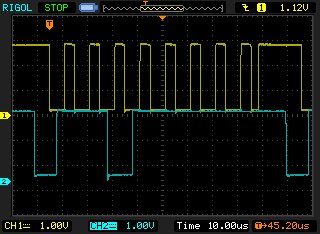
Interestingly, we are communicating between the CC3200 (muxed to default pins 1 and 2) and the ST Micro M41T62 which happens to have the same address (0xD0). Also interesting, the CC3200 is getting into a state where it incorrectly transmits 0xDF, exactly as in the scope trace in the original post.
Our I2C code works OK the first time the CC3200 is programmed, however after debugging/reprogramming several times I2C communication breaks on some units... Cycling power and reprogramming the part does not seem to help.
-Dave
Hi Jan,
We are getting the same error: I2C_MASTER_ERR_ARB_LOST.
Strangely, this occurs when no slave device exists on the bus (we removed the slave peripheral to test whether it was pulling SDA low incorrectly). Here is a trace of the I2C message with probes directly on CC3200 output pins, no slave, only 2k pullups connected. Firmware is programmed to transmit 0x53, however we see 0xDF incorrectly (as with the original post):
I do not see how arbitration can be lost with only the CC3200 on the bus, unless it is an internal pin-mux issue. We are using default pin1 and pin2 however, so I wouldn't think initializing pin3 and pin4 after I2C initialization should matter...
This is our initialization code, generated by the TI pinmux utility:
void PinMuxConfig(void)
{
//
// Enable Peripheral Clocks
//
MAP_PRCMPeripheralClkEnable(PRCM_ADC, PRCM_RUN_MODE_CLK);
MAP_PRCMPeripheralClkEnable(PRCM_GSPI, PRCM_RUN_MODE_CLK);
MAP_PRCMPeripheralClkEnable(PRCM_I2CA0, PRCM_RUN_MODE_CLK);
MAP_PRCMPeripheralClkEnable(PRCM_GPIOA0, PRCM_RUN_MODE_CLK);
MAP_PRCMPeripheralClkEnable(PRCM_GPIOA1, PRCM_RUN_MODE_CLK);
MAP_PRCMPeripheralClkEnable(PRCM_GPIOA2, PRCM_RUN_MODE_CLK);
MAP_PRCMPeripheralClkEnable(PRCM_GPIOA3, PRCM_RUN_MODE_CLK);
//
// Configure PIN_05 for SPI0 GSPI_CLK
//
MAP_PinTypeSPI(PIN_05, PIN_MODE_7);
//
// Configure PIN_06 for SPI0 GSPI_MISO
//
MAP_PinTypeSPI(PIN_06, PIN_MODE_7);
//
// Configure PIN_07 for SPI0 GSPI_MOSI
//
MAP_PinTypeSPI(PIN_07, PIN_MODE_7);
//
// Configure PIN_01 for I2C0 I2C_SCL
//
MAP_PinTypeI2C(PIN_01, PIN_MODE_1);
//
// Configure PIN_02 for I2C0 I2C_SDA
//
MAP_PinTypeI2C(PIN_02, PIN_MODE_1);
//
// Configure PIN_03 for GPIO Input
//
MAP_PinTypeGPIO(PIN_03, PIN_MODE_0, false);
MAP_GPIODirModeSet(GPIOA1_BASE, 0x10, GPIO_DIR_MODE_IN);
//
// Configure PIN_04 for GPIO Input
//
MAP_PinTypeGPIO(PIN_04, PIN_MODE_0, false);
MAP_GPIODirModeSet(GPIOA1_BASE, 0x20, GPIO_DIR_MODE_IN);
}