This thread has been locked.

If you have a related question, please click the "Ask a related question" button in the top right corner. The newly created question will be automatically linked to this question.

CC3100 file corruption when writing to file when connected to a network with multiple sockets active

Other Parts Discussed in Thread: CC3100, UNIFLASH, CC3200

Our application is utilizing a FTP client to download user file updates when we want to update our system. To do this, we connect the CC3100 to a WLAN, and then connect to a FTP server and download each file that needs to be updated. The FTP client will read 512 bytes at a time from the FTP data socket, and write the contents to a file in the CC3100's file system. We have noticed that occasionally it looks like some of the file writes aren't completing, because after each write to the file, we read the same location in the file back to verify that the contents were successfully written. Every time we see a failure, it looks like the last 8 bytes of the write aren't completing, because those 8 bytes are always 0xFF. We have captured the SPI traffic between the host and CC3100, and have verified that the sl_FsWrite() command contains the correct data, so we think the write at least looks successful. I have attached the sl_FsWrite() and subsequent sl_FsRead() transfer to show all SPI data leading up to the failure. It should be noted that whenever the failure occurs, even though we attempt to read 512 bytes from the socket, we get back a much smaller amount of data (40 bytes in this case). There are other cases where we get back a smaller amount of data and the file write works, so it doesn't fail every time that happens.

Any idea what could be happening?

file_readback_mismatch.pdf

  • Hi,

    I do not see the relation to FTP in parallel.

    Can you please elaborate the followings:

    • what service pack are you using?
    • how do you open the file? what attributes/flags are you using? can you share a code snippet?

    Shlomi

  • Hi Shlomi,

    I agree that FTP is not an issue here; just wanted to provide a context for what the application is doing.

    We are using service pack v1.0.1.6-2.6.0.5.

    The way we use the file system is when we first configure the device, we format the flash and then create all the application files once. From that point on, we simply overwrite them when we change them. I'm supplying a snippet of the code in question. The general flow in our application is:

    - Establish FTP connection with FTP server with non-blocking control and data socket

    - Open file on CC3100 that is the destination for the downloaded file

    - Poll the data socket every 50ms for 512 bytes of data

    - When data is returned from the socket, a callback function is executed (shown below)

    -------------------------------------------------------------------------

    int32_t fileHandle;
    const char *fileNamePtr;
    uint32_t totalBytesRead = 0;
    int32_t writeStatus;
    int32_t readStatus;
    
    <snip>
    
    // file is opened after FTP data connection is established
    fileHandle = sl_FsOpen( fileNamePtr,
                            FS_MODE_OPEN_WRITE,
                            NULL,
                            &fileHandle );
    
    <snip>
    
    <at this point, socket returned "socketResult" bytes of data, and the following code is executed>
    
    // Data read successfully, so store to file
    writeStatus = sl_FsWrite( fileHandle,
                              totalBytesRead,
                              DATA_BUF_ADDR,
                              socketResult );
    
    // Read back data and compare to what was written
    if (writeStatus == socketResult)
    {
        readStatus = sl_FsRead( fileHandle,
                                totalBytesRead,
                                COMPARE_BUF_ADDR,
                                socketResult );
        if (readStatus == socketResult)
        {
            // read back correct number of bytes, now compare
            if (memcmp( DATA_BUF_ADDR, COMPARE_BUF_ADDR, socketResult ) != 0)
            {
                GPIO_OUT_SET_HIGH( P44 ); // set GPIO to trigger logic analyzer
                compareError = TRUE;
            }
            else
            {
                // update number of bytes read
                totalBytesRead += socketResult;
            }
        }
    }
    
    <snip>
    

  • Hi,

    When you say "occasionally", what do you mean? how often does it happen? is it random?

    In any case, I would like you to test something. Can you please close the file and open it for READ before reading?

    I am asking becasue the proper way to work with the file system is by openning it to specific mode before working in this mode. Openning for WRITE and do actual READ is not the right way to work.

    Regards,

    Shlomi

  • Hi Shlomi,

    It happens randomly -- I have been running a test that constantly FTPs the files we're updating (6 files each time), and it happens from 3 to 8 times in a 12 hour period. So not too frequently.

    I can test your suggestion, but that's essentially what we were doing when we first discovered this issue. The way our system originally worked was we would 1024 bytes at a time from the socket, calculate a running CRC32 on the data, and write the received data to the file. Then, after the transfer was completed and the file was closed, we would re-open the file, read the file contents, calculate a CRC32 on that, and verify the 2 CRC32's matched (which they did not when it failed).

    I'll try your suggestion with my current implementation and let you know what I find.

    Thanks,
    -Ed
  • Hi Shlomi,

    I tried your suggestion and reverted back to our original implementation. What we do for each file is:

    1) Open file for write
    2) Receive file contents via FTP 1024 bytes at a time. Each packet received from the FTP socket is written to the file. A running CRC32 is performed on the data as it is received.
    3) When the transfer is complete, we close the file and compare the CRC32 of the received data against an expected CRC32 value. If it matches, we continue.
    4) Open file for read. Read the contents 512 bytes at a time, and calculate a running CRC32 on the data read from the file.
    5) Close file
    6) If all CRC32 values match, we consider the download a success.

    I ran this implementation last night, and I got 7 failures out of 3054 total file downloads. Every failure was that the CRC32 calculated in step 4 did not match the expected CRC32. So it seems the failure rate is roughly the same as the method I originally described. I played around with modifying the method I originally described to close the file and open for read when I compared the contents of each packet, but implementing the "file append" procedure in the serial flash guide is very time consuming since the file is erased every time it is opened for write. Thus, that option is a non starter.

    I would prefer to debug this using my originally described method of comparing received packets immediately since it catches the failure when it happens instead of after the complete file is downloaded (in case a logic analyzer trace is required).

    Any ideas on how to track down the cause of this issue?

    Thanks,
    -Ed
  • Hi Ed,

    I would like to understand more. Can you tell whether it is always 8 bytes of 0xFF or do you get other number of bytes and other than all 0xFF?

    From your description it is still not conclusive whether it is the write transaction that fails or the read transaction that fails. The SPI lines capture is for the SPI lines going between the host and the device and not the device and the serial flash.

    To clarify, I suggest the followings:

    1. make sure that the return value from sl_FsWrite() indicates the expected number of bytes
    2. to test the FsRead()
      1. is it always 8 bytes with 0xFF
      2. if so, can you please read again from the offset where it is 0xFF and check whether it is still 0xFF or the actual expected data?

    Shlomi

  • Hi Shlomi,

    The incorrect data is always 0xFF, but the amount of incorrect data does vary.

    I believe our code already verifies that the return value from sl_FsWrite() is correct.

    I will try your suggestion of re-reading the data when it does not match. Should I also capture the SPI bus from the CC3100 to the serial flash on a logic analyzer?

    Thanks,

    -Ed

  • Hi Ed,

    The SPI lines you shared before are between the host and the device so capturing the SPI lines to the serial flash would add more info.

    The fact that it is always 0xFF makes me believe that it might be related to the actual write since it is an erased location but it might be just leftovers on the SPI lines, not sure.

    Please execute the suggested tests so we can have the full picture before we conclude anything.

    Thanks,

    Shlomi

  • Hi Shlomi,

    I was able to implement the code to retry the file read when I detected a failure, and I verified that the additional reads still provided incorrect data. So it's looking like the failure is indeed on the file write.

    I will hopefully be able to capture the serial flash SPI activity associated with the failure and provide those results tomorrow. If you have any other suggestions of things to try, please let me know.

    Thanks,
    -Ed
  • Hi Ed,

    Let's keep the flash SPI lines capture as the only test for now.

    If we do see that it is a write issue, I would request you to dump the entire flash.

    Please let me know what is the size of the flash and whether it is OK to provide you with a windows utility that connects to the device over UART (the same as Uniflash does) and read the entire flash.

    Regards,

    Shlomi

  • Hi Shlomi,

    I should be able to run my test again tomorrow. In the meantime, we're using a 16 Mbit flash part from Winbond. If necessary, I would be willing to dump the contents of flash using your Windows utility.

    Thanks,
    -Ed
  • Hi Shlomi,

    I was able to capture the activity on the SPI bus between the CC3100 and the serial flash. I'm attaching the SPI activity between the file write of the received packet and the subsequent readback of the same data. As can be seen, not all of the data is written to the serial flash... it looks like the first 32 bytes of the data is written, and then the CC3100 starts reading the status of the flash. The thing that looks odd to me is I see 2 commands to read the serial flash status, followed by reads of 0x03, which I think means the flash is busy, but then the CC3100 issues a Set Write Enable command (0x06), followed by a lot of serial flash status commands, with reads of 0x03. Then I see the result of the serial flash status command be 0x01, followed by 0x00. Then the CC3100 issues 1 more serial flash status command, followed by a resultant read of 0x00, and then the CC3100 appears to give up on the write. About 700 usec later, I see the serial commands associated with the file read, which contains 0xFF in the data addresses that weren't written.

    I've attached the decoded SPI data that goes with my description above. If you want, I saved my logic analyzer capture (done with a Saleae analyzer), if you want the whole thing (it's about 21Mbytes).

    By the way, my logging output is also shown to see what data we attempted to be written, and what was read back. Please let me know if you need to see anything else.

    Thanks,

    -Ed

    [00149] FTP-MGR : Mismatch between source and destination data - retrying read...
    [00150] FTP-MGR : Mismatch between source and destination data - retrying read...
    [00151] FTP-MGR : Fatal mismatch between source and destination data!!!!
    [00152] FTP-MGR : Data length: 46
    [00153] FTP-MGR : Source data:
    421AC243562E10011D830230CD180C5C
    1001FC40330000001001FC4022000000
    100132D01000FD3FC243562E1001
    [00154] FTP-MGR : Destination data:
    421AC243562E10011D830230CD180C5C
    1001FC40330000001001FC4022000000
    FFFFFFFFFFFFFFFFFFFFFFFFFFFF

    serial_flash_activity.pdf

  • Thanks Ed for the information. It does look as write issue but I need to take a closer look. I can do it early next week.

    Meanwhile, I am intrested to know few more things:

    1. you mentioned it happens few times in 12 hours. Is it possible to get the data as above for more than one occurance (not the SPI captures but the actual data prior to the 0xFF)? I want to make sure it is not something in the payload
    2. when it happens, can you tell the return value from FsWrite()? I want to make sure that all bytes were assumed to be written and that you don't get out of offset error

    Again, will look into it early next week again.

    Shlomi

  • Hi Shlomi,

    I've included the data from 2 consecutive failures below. In all cases, the return value from FsWrite() matches the number of bytes received from the socket. My code is written such that if the return values from the FsWrite() or FsRead() calls do not match the number of bytes received from the socket, I flag a failure. Since we're getting the results shown below, that implies the FsWrite() and FsRead() calls have return values that are as expected.

    I will be out until Tuesday, so if you need me to provide any other information, please let me know.

    Thanks,

    -Ed

    ------------------------------

    [00149] FTP-MGR : Mismatch between source and destination data - retrying read...
    [00150] FTP-MGR : Mismatch between source and destination data - retrying read...
    [00151] FTP-MGR : Fatal mismatch between source and destination data!!!!
    [00152] FTP-MGR : Data length: 156
    [00153] FTP-MGR : Source data:
    C0F33D403805B113F0302C4200185C52
    7C2CB113EA310C431001B2D010004007
    B2F0FCFF4007B2F0C0FF5A07B2F07FF0
    40073F400FF01FF242073FD00802824F
    4207B2F0F7FC4407B2D08100B0011F42
    B0011FF2B0013FF0CFFF824FB0013C40
    4B00B113D629B2F0F9FF4207B2D01400
    44073F4080FF1FF24A073FD01400824F
    4A07B2D00300400792B35C07FD273C40
    FF031CF2520792C3B001B2F0
    [00154] FTP-MGR : Destination data:
    C0F33D403805B113F0302C4200185C52
    7C2CB113EA310C431001B2D010004007
    B2F0FCFF4007B2F0C0FF5A07B2F07FF0
    40073F400FF01FF242073FD00802824F
    4207B2F0F7FC4407B2D08100B0011F42
    B0011FF2B0013FF0CFFF824FB0013C40
    4B00B113D629B2F0F9FF4207B2D01400
    FFFFFFFFFFFFFFFFFFFFFFFFFFFFFFFF
    FFFFFFFFFFFFFFFFFFFFFFFFFFFFFFFF
    FFFFFFFFFFFFFFFFFFFFFFFF

    and

    [00165] FTP-MGR : Mismatch between source and destination data - retrying read...
    [00166] FTP-MGR : Mismatch between source and destination data - retrying read...
    [00167] FTP-MGR : Fatal mismatch between source and destination data!!!!
    [00168] FTP-MGR : Data length: 46
    [00169] FTP-MGR : Source data:
    421AC243562E10011D830230CD180C5C
    1001FC40330000001001FC4022000000
    100132D01000FD3FC243562E1001
    [00170] FTP-MGR : Destination data:
    421AC243562E10011D830230CD180C5C
    1001FC40330000001001FC4022000000
    FFFFFFFFFFFFFFFFFFFFFFFFFFFF

  • Hi Ed,

    I asked one of our R&D expert to take a look and see whether something is wrong on the SPI lines.

    Is it possible to upload the logicdata as well (saleae).

    Shlomi

  • Hi Shlomi,
    Sure, no problem. Do you want the SPI between the host and CC3100, or between the CC3100 and the serial flash?
    Thanks,
    -Ed
  • Hi Shlomi,

    I tried to upload a capture (.logicdata format) of the SPI traffic between the host and the CC3100, but I received an error (all I got was a red box with no text, so I'm not sure what happened). If you want, I can send you the file separately; please let me know where to send it. My capture is 5 Mb, so it should be able to be sent in an e-mail.

    Thanks,

    -Ed

  • Hi Ed,

    Is it possible to upload it to google driver (or any other cloud drive)?

    Additinally, the best way to debug here is to extract logs from the network processor itself.

    There is a way to do if you can connect to pin #62, denoted as CC_NWP_UART_TX.

    Let me know if possible.

    Shlomi

  • Hi Shlomi,

    Here is a link to the capture from yesterday: 

    I'm trying to get a new capture with the CC_NWP_UART_TX pin added, but the process hasn't failed yet. When it does, I'll create a link to that capture as well. By the way, what are the UART settings (i.e. baud rate, start/stop bits, etc) used on CC_NWP_UART_TX?

    Thanks,

    -Ed

  • Ed,

    The procedure is as follows:

    1.     Identify the hardware pin for network logger on CC3200 chipset.
    1.     For CC3200 QFN flavor, it is pin #62 (GPIO07)
    2.     For CC3200 MOD flavor, it is pin #52 (GPIO07)
    2.     Use a level shifter and connect ground and the 1-pin data line
    3.     Add to pinmux.c the following lines:
    1.     MAP_PRCMPeripheralClkEnable(PRCM_UARTA0, PRCM_RUN_MODE_CLK);
    2.     MAP_PinTypeUART(PIN_62, PIN_MODE_1);
    4.     Open a terminal emulation and configure the followings:
    1.     baud rate: 921,600 bps
    2.     8 bits
    3.     no parity
    4.     1 stop bit
    5.     no flow control
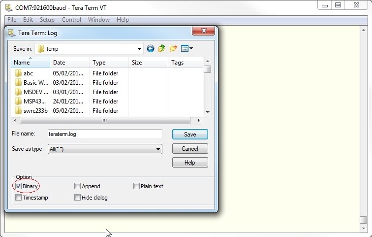
    5.     Configure the terminal emulation to work in Binary mode (and not textual/ASCII mode)
    6.     Configure the terminal emulation to work in "Log" mode so any character that is received from CC3200 chipset device is written to the local Log file. In this phase, binary characters should appear on the terminal window.
    7.     Close the log file when done and send it to TI for post capture analysis.

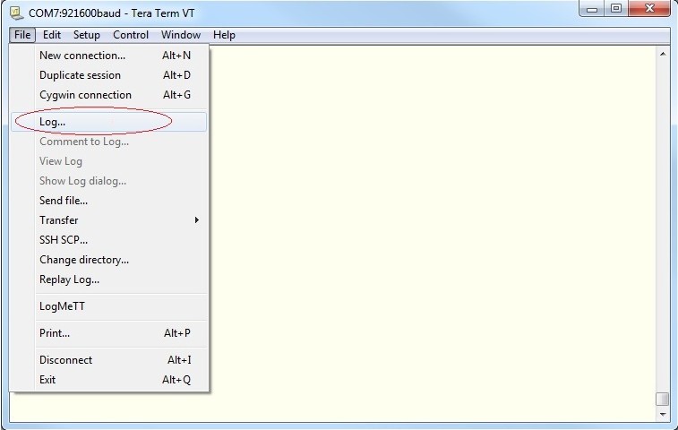
    For reference, TeraTerm terminal emulation is shown for example:

    1. Open a terminal emulation and configure the followings:
      1. baud rate: 921,600 bps
      2. 8 bits
      3. no parity
      4. 1 stop bitflow control
      5. no flow control

    2. Configure the terminal emulation to work in Binary mode

    3. Configure the terminal emulation to work in "Log" mode

    Shlomi

    The procedure is as follows:

    1.     Identify the hardware pin for network logger on CC3200 chipset.
    1.     For CC3200 QFN flavor, it is pin #62 (GPIO07)
    2.     For CC3200 MOD flavor, it is pin #52 (GPIO07)
    2.     Use a level shifter and connect ground and the 1-pin data line
    3.     Add to pinmux.c the following lines:
    1.     MAP_PRCMPeripheralClkEnable(PRCM_UARTA0, PRCM_RUN_MODE_CLK);
    2.     MAP_PinTypeUART(PIN_62, PIN_MODE_1);
    4.     Open a terminal emulation and configure the followings:
    1.     baud rate: 921,600 bps
    2.     8 bits
    3.     no parity
    4.     1 stop bit
    5.     no flow control
    5.     Configure the terminal emulation to work in Binary mode (and not textual/ASCII mode)
    6.     Configure the terminal emulation to work in "Log" mode so any character that is received from CC3200 chipset device is written to the local Log file. In this phase, binary characters should appear on the terminal window.
    7.     Close the log file when done and send it to TI for post capture analysis.

    For reference, TeraTerm terminal emulation is shown for example:

    1.     Open a terminal emulation and configure the followings:
    1.     baud rate: 921,600 bps
    2.     8 bits
    3.     no parity
    4.     1 stop bit
    5.     no flow control

    2.     Configure the terminal emulation to work in Binary mode

    3.     Configure the terminal emulation to work in "Log" mode

    Shlomi

  • Hi Shlomi,
    We're using the CC3100. Is the procedure the same as for the CC3200, except without the code modifications?
  • the procedure is the same, just connect to the correct NWP log pin.

  • Hi Shlomi,

    I was able to capture the issue again. The only issue is since I need to let it run for a long time, it was not practical to dump the UART data to a file. I captured it along with the host SPI as well as a separate GPIO to trigger the logic analyzer when the failure is detected. I saved the log analyzer trace here: 

    I also dumped a section of the UART Tx data to a .csv file here: 

    Thanks,

    -Ed

  • Hi Shlomi,

    Were you able to access the files I linked in my previous post? Do you need any further data from me?

    Thanks,

    -Ed

  • Ed,

    For some reason I am not able to open the logicdata file.

    I am using Saleae 1.1.15.

    Regardless, have you managed to capture the NWP logger? this logger is the most important log.

    Regards,

    Shlomi

  • Hi Shlomi,

    I'm using the latest version from (1.1.20 I think).

    The other file is a .csv of the UART data associated with the logic analyzer capture. If that's unusable too, I can get another capture tomorrow and put the UART data in a text file if you want. At the very least, can you look at the .csv data and see if it looks like the UART data you would typically expect?

    Thanks,

    -Ed

  • Ed,

    Maybe I am missing something but what UART interface are you capturing? is it the NWP logger I mentioned?

    In any case, I need the NWP logger in its raw binary format since I need to do some post processing on the file to make it readable.

    I know it might be a large file but there is no other way.

    Shlomi

  • Hi Shlomi,

    I did capture the NWP UART Tx interface, but I was hoping you could convert from either the logic analyzer trace or the .csv file into what you need. I'll do another capture tomorrow with the NWP UART logged to a file and provide a link to the output.

    Thanks,
    -Ed
  • Hi Ed,

    Please follow the instructions carefully. The baud rate is important as well as recording in binary mode so no extra characters are added/removed (as happens when working in ASCII mode for example).

    Shlomi

  • Hi Shlomi,

    I think I got what you need. Luckily the failure happened pretty fast, so the file isn't too big. You can find it here:

    https://drive.google.com/open?id=0B4vJQiUGgCrISFZUNFVKajJKbjQ

    Please let me know if this is what you're looking for, and if you need any more captures.

    Thanks,

    -Ed

  • Hi Ed,

    Thanks for the detailed captures.

    In the logger file I can see the transactions as far as the NWP is concerened.

    I can see that the last 40 bytes of aprocfw0 are written and then read beak. I guess this is where your problem is.

    The logger does not show reading of 32 bytes but the entire 40 bytes so the problem might be on the lower levels of the SFLASH driver.

    I have looped in R&D for assistance on this one and will let you know once I have feedback from them.

    Regards,

    Shlomi

  • Hi Ed,

    R&D has just replied and occurance of such case cannot be explained.

    If it is not too hard, would it be possible to conduct a combined test with the following captures:

    1. loggic captures of the SPI transactions between the device and the serial flash as before but this time also with CS line? this line is important for the post analysis
    2. NWP logger as before

    Also please state where it fails, e.g. when writing file XXX.

    Lastly, can you verify the signal integrity, i.e. that the signal is "clean" and does not suffer from fluctuations. Usually it can be seen only on analog signals. Also, have you seen unpredictable behaviors before with the file system/serial flash?

    Again, sorry for the extra testing but since you can reproduce it on your side, it would be the fastest way to bring it to resolusion.

    Thanks,

    Shlomi

  • Hi Shlomi,

    I've got a new capture for you as requested. The version of the Saleae analyzer I'm using is 1.2.10. I've captured the host SPI interface in addition to the flash SPI interface. The CS lines are labeled as "SPI enable". The "trigger" signal is the host application detecting the data mismatch as noted in the log below. By the way, would it be possible for me to get a copy of whatever tool you run on the NWP logger output to analyze the data? It looks like it would be handy to debug WLAN issues here! Anyway, I did try to look at the signal integrity using Saleae's analog settings, but I think the clock on the serial flash SPI is too fast for it to keep up, so we're going to look at it with a regular scope. I'm assuming the SPI clock is what you would want us to verify - are there any others?

    I looked at the flash SPI activity before the failure, and as was the case before, the last 8 bytes of the data block shown in the log below are not being written to the serial flash. From what I can tell, there are a lot of reads of the Windbond status register coming back indicating it is busy. The last 2 reads indicate the busy condition is cleared, but perhaps the SFLASH driver had already timed out which is why the data didn't get written?

    Please let me know if you need any more data, and thanks again for your help! See below for the links to the files as well as a copy of my application log output.

    -Ed

    -----------------

    The logic analyzer output is here: https://drive.google.com/open?id=0B4vJQiUGgCrIa0QwUzZYeW10MjA 

    The NWP logger output is here: https://drive.google.com/open?id=0B4vJQiUGgCrIQUpfbXZlU19vZzA


    The file that the failure occurred on is AprocFW0, and the output from my log is this:

    Retrieving file fw1411-tag\0001.bin into AprocFW0
    
    [00077] WLAN-DBG        : Tx send started
    [00078] WLAN-DBG        : Tx send started
    [00079] FTP-MGR-DBG     : Length of file fw1411-tag\0001.bin is 109056, max length is 131072
    [00080] WLAN-DBG        : AprocFW0 open status = 0
    [00081] WLAN-DBG        : Socket connect started          
    [00082] FTP-MGR-DBG     : Data socket connect callback result: 0
    [00083] WLAN-DBG        : Tx send started   
    [00084] FTP-MGR         : Mismatch between source and destination data!!!!
    [00085] FTP-MGR         : Data length: 40
    [00086] FTP-MGR         : Source data:                             
    D85AC243D65A10017D4033007E404400                                      
    7F43B2135A8E0C9306248C0122493D40                                            
    180780008CF91001
    
    [00087] FTP-MGR         : Destination data:
    D85AC243D65A10017D4033007E404400                                 
    7F43B2135A8E0C9306248C0122493D40
    FFFFFFFFFFFFFFFF
    
    [00088] WLAN-DBG        : Close file status = 0
    [00089] FW-MGR          : Next image to download is type 0, slot 0.
    

  • Hi Shlomi,

    I'm also providing a different version of the same logic analyzer capture, except I have placed a marker at what looks to me to be a suspicious transaction on the flash SPI bus in the area where the cc3100 does not write the 8 bytes of data in question. In previous successful transactions, I see a pattern of writes of the command 0x05 (Read status register 1), followed by data of 0x03 when the Winbond device is busy with the previous write. When the write is finished, the returned data is 0x00. Then I saw command 0x06 (Write Enable), followed by more reads of the status register. So the "good" pattern I saw earlier is something like this:

    write 0x05

    read 0x03

    write 0x05

    read 0x03

    .

    .

    .

    write 0x05

    read 0x00

    write 0x06

    The suspicious activity I see is this:

    write 0x05

    read 0x03

    write 0x05

    read 0x03

    write 0x06

    I don't know if this indicates something is wrong, but it looks odd to me.

    Here is the link to this capture: https://drive.google.com/open?id=0B4vJQiUGgCrIeFk0OTNOeWFLbVE

    Thanks,

    -Ed

  • Hi Shlomi,

    Any update on your end? On our end, we've verified that the SPI clock does nothing abnormal when the failure occurs. Are there other signals we should check? Also, would you be able to share the tool you run on the NWP UART captures?

    Thanks,

    -Ed

  • Hi Ed,

    Sorry for the delay.

    I have just downloaded your files and will give it a look early tomorrow.

    Regarding a tool to extract the log binary, unfortunatelly it is R&D internal tool so it is not for sharing.

    Will update you tomorrow on the progress.

    Regards,

    Shlomi

  • Hi Ed,

    We are looking into it and came to the same conclusions as you did regarding the strange behavior of the commands to the serial flash.

    Next phase is to look for this behavior on the flash driver itself.

    Will update as soon as we find a logic explenation for it.

    Thanks,

    Shlomi

  • Hi Ed,

    Just one more question.

    What is the exact part number of the Winbond part you are using?

    Shlomi

  • Hi Shlomi,

    We are using W25Q16DWSSIG.

    Thanks,
    -Ed
  • Hi Ed,

    We were not able to identify a possible root cause on out low level drivers.

    The only way it could happen is if the signal on the MISO line from the serial flash is not detected correctly which may imply signal integrity.

    We have requested before to capture with an analog loggic the integrity of the SPI clock signal.

    I highly recomment to also capture the MISO line from serial flash to the device.

    It is sufficient to capture only the few 10s of mSec before the trigger is latched and then analyze the integrity of the clock and the MISO lines (we are mostly interested to see the result of the read status register since the write enable command is executed where it should not).

    One other thing, I have noticed you are using a 1.8V serial flash which implies you are working in a pre-regulated fashion with the device. Is this correct?

    If so, can you please make sure the voltage supply to the serial flash and to the device is the same?

    Lastly, I would suggest an easy test to work around the issue on host level.

    When you detect this case, can you try to rewrite the missing bytes again and let me know if it works (previously I asked to re-read and verify it is all 0xFF)?

    Thanks,

    Shlomi

  • Hi Shlomi,

    Thank you for the update. We are analyzing the MISO line to see if there's an integrity issue. I have been working around the issue by re-issuing the write, and it seems to work fine. The main thing I was worried about was that the files that the CC3100 use internally are potentially getting corrupted as well. But maybe the CC3100 firmware already takes care of that scenario?

    I'll update you when we know more about the MISO line.

    Thanks,
    -Ed
  • Hi Shlomi,

    One more thing - would it be possible for you to send me a CC3100 patch that asserts a GPIO (if one is available) when the flash driver times out on a write (assuming that's what happens when the data doesn't get written)? That would help us greatly on our side in getting a scope to trigger deterministically when the root cause of the issue occurs.

    Thanks,
    -Ed
  • Ed,

    Please let me know when you have something.

    Theoretically, it can also happen on system files but we have not been reported on such cases before.

    Let's first get to the root casue and understand whether it is signal integrity issue or not.

    Also, please reply regarding the pre-regulated voltage.

    Thanks,

    Shlomi

  • Ed,

    It’s not a timeout issue but more likely a bad read of the status register.

    The NWP will not necessarily detect the problem and reading back the data will so at the moment I suggest reading it back on host level to detect as you do.

    Shlomi

  • Hi Shlomi,

    OK, I have a somewhat better feel for what is going on. First of all, we are powering the CC3100 at 2.2V and the serial flash at 1.8V (both regulated), so you are correct that the voltage differential is likely a big contributing factor to the issue. The only time we see corruption is when the CC3100 is connected to a WLAN, and it just so happens that the MISO line of the SPI connected to the serial flash is routed very close to the antenna. We have several potential solutions running in parallel, and it's not clear yet what will completely fix it. We have done the following:

    1) Placed a level shifter on the MISO line to have it at a 2.2V level to match the CC3100. The part we're using introduces almost no delay, so timing should still be well within margin. We have 2 different board designs with this change - the board I've been using was a previous design where MISO was routed far away from the antenna, and my board ran failure free for 3 days. The same change was applied to a newer board layout where MISO is close to the antenna. In this case, it fails one or twice a day (i.e. a lot less frequently), but now the failure is that a single bit in the payload is a 0 when it should be a 1. Interestingly enough, the failure seems to occur on the write to the serial flash, because I added the change to where I read the data back multiple times when a failure is detected, and it's always the same single bit that is wrong. We're going to dig into this one further as it doesn't make sense to us.

    2) Modified a board to have the CC3100 and serial flash both running at 1.8V. This is mainly to see if the issue goes away without rerouting any signals, but for us this would not be acceptable due to the extra hibernate current that is a byproduct of this solution.

    Thank you so much for all your help with this issue. Do you think this solution will be OK?

    Thanks,
    -Ed
  • Hi Ed,

    Let me start by saying I am not an HW expert but I did some digging and few notes are important:

    • it is not a good practice to have different voltage supplies on CC3100 and the serial flash. It can lead to current flow because of the voltage gap and can also influence on signal integrity and pulls (pull up and pull down)
    • using level shifter may be OK but you need to apply it on all 4 lines (MISO, MOSI, CS and CLK)
    • from your description of working in regulated 2.2V with CC3100, I understand you are working with batteries and want to same some power and as such extend the lifetime of the product. Please note that the margin left is 0.1V since CC3100 operates from 2.1V. You need to be very careful as not to drop below especially in corner cases such as calibration procedure that takes place upon power on. Calibration draws a lot of current from the batteries (few hundreds of mAmps)
    • Also, corner cases such as temperatures such as -40C and +80C

    Regards,

    Shlomi

  • Hi Ed,

    Any update on this post?

    Should we keep it open or can I close it?

    Regards,

    Shlomi

  • Hi Shlomi,

    Sorry for the delayed response, but we wanted to make sure our changes ran for several days with no errors, which we can now say is true. Putting the level shifter in the serial flash MISO line got rid of the errant status register read (which led to the 3100 not completing the write of the data), but we then had an issue where every once in a while we would see that 1 bit in the data was set to a 0 when it should have been a 1. We were originally thinking this had something to do with the MISO line being routed close to the antenna, but it turned out that we needed to place a larger capacitor on the Vcc pin on the serial flash part. With these 2 changes, everything works great.

    Thank you again so much for helping us track down the cause of the problem! We can close this issue now.

    Thanks,
    -Ed
  • Sure Ed, I was happy to assist and see that everything works now.

    The debug capabilities on your side (which is not trivial) made it possible to track down the root cause.

    Regards,

    Shlomi