


Hi,
I have got the spi active and have tested the working of SCLK, MOSI and CS w.r.t the program. While testing, I noticed some of the following issues such as:
1. The CS line and Clock signals are not synchronized
2. The data bits clocked out from MOSI are not matching with the actual data byte being sent
3. Sometimes, the data out is clocked out even before the start of the clock signal and I was wondering how can this be possible.
SPI configured for Bit Rate of : 100 KHz
SPI Sub Mode : 0 i.e. If I have understood it right -- The data is sampled on the rising edge of the clock signal and the data bit is clocked out during the falling edge of clock signal
SPI Mode: MASTER
The FIG(1) below shows the image with the CRO output for the issue (1).
 FIG (1)
The Blue line is the CS signal and the Yellow one is the clock signal. As it can be seen in the CRO, the start of the clock signal has been delayed a while later than the CS signal is triggered. Isn't the clock signal supposed to start as soon as the CS signal has been triggered?.
The FIG(2) below shows the CRO output that addresses the issue (2) relevant data mismatch. The Blue line is data line and Yellow one is clock signal

FIG (2)
In FIG (2), I have transmitted a character "A" i.e 0x0A. The expected data output bits supposed to be (MSB) 0000 1010 (LSB) in binary w.r.t the eight clock cycles shown above. However, form my perception of the signals, I am getting some other data at the output and not 0x0A. Please let me know me if the data out what I am getting is actually wrong or I have interpreted the signals in a wrong way. This same issue applies to FIG (3) below as well when I transmit a character "B" i.e. 0x0B.
 FIG(3)
Just for more information, I am also attaching an image below in FIG(4), which show the transmission of 5 bytes i.e. "ABCDE"
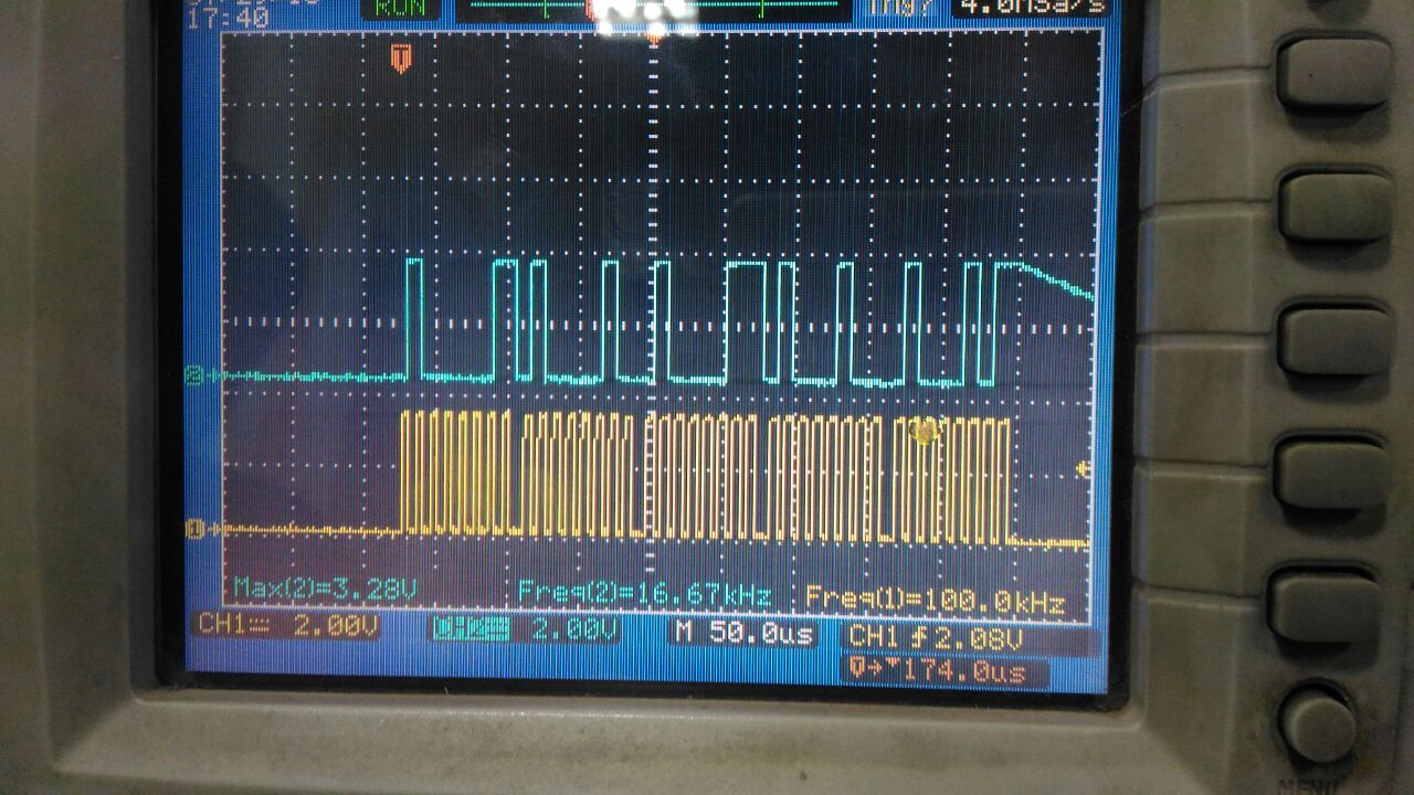 FIG(4)
The FIG(5) below shows the CRO output that addresses the issue (3) relevant data being generated even before the start of the clock signal. The Blue line is data line and Yellow one is clock signal.
 FIG(5)
In FIG (5), I have transmitted a character "F" i.e 0x0F. The expected data output bits supposed to be (MSB) 0000 1111 (LSB) in binary w.r.t the eight clock cycles shown above. Here too, I am getting some other data as well as , it can be seen that the data out is clocked out before the clock signal and there is not sync between the clock and the data.
Below is the software/program I used while performing these tests in master mode, which is a slight modification of the actual spi_demo example :
#define MASTER_MODE      1

#define SPI_IF_BIT_RATE  100000
#define TR_BUFF_SIZE     100

//Default start strings
#define MASTER_MSG       "ABCDEFGHIJ"
#define SLAVE_MSG        ""

void MasterMain()
{

	int i;
        int bytecount = 1;
	    unsigned long ulUserData;
	    unsigned long ulDummy;


	    memcpy(g_ucTxBuff,MASTER_MSG,sizeof(MASTER_MSG));

	    ucTxBuffNdx = 0;
	    ucRxBuffNdx = 0;


	    MAP_SPIReset(GSPI_BASE);

	    MAP_SPIConfigSetExpClk(GSPI_BASE,MAP_PRCMPeripheralClockGet(PRCM_GSPI),
	                     SPI_IF_BIT_RATE,SPI_MODE_MASTER,SPI_SUB_MODE_0,
	                     (SPI_SW_CTRL_CS |
	                     SPI_4PIN_MODE |
	                     SPI_TURBO_OFF |
	                     SPI_CS_ACTIVELOW |
	                     SPI_WL_8));

	    MAP_SPIEnable(GSPI_BASE);

	    Message("Enabled SPI Interface in Master Mode\n\r");
	    Report("Press any key to transmit data....");

		while(1)
		{
			ulUserData = MAP_UARTCharGet(UARTA0_BASE);

			MAP_SPITransfer(GSPI_BASE,g_ucTxBuff,0,bytecount,
					SPI_CS_ENABLE|SPI_CS_DISABLE);

			Report("\r\n\nSending:");
			for(i = 0; i < size; i++)
			{
				Report("%c", g_ucTxBuff[i]);
			}
			Report(":");

			Report("\r\nReceived:%s:",g_ucRxBuff);
			for(i = 0; i < size; i++)
			{
				Report("%02X, ", g_ucRxBuff[i]);
			}
			Report(":\r\n");

		}
	}
Any help, information or advise on changes to be made regarding this would be appreciated. Thanks in advance.
Regards
~VD
