This thread has been locked.

If you have a related question, please click the "Ask a related question" button in the top right corner. The newly created question will be automatically linked to this question.

CC3200: Not able to Format CC3200 by using UART.

Part Number: CC3200
Other Parts Discussed in Thread: UNIFLASH,

Hi,

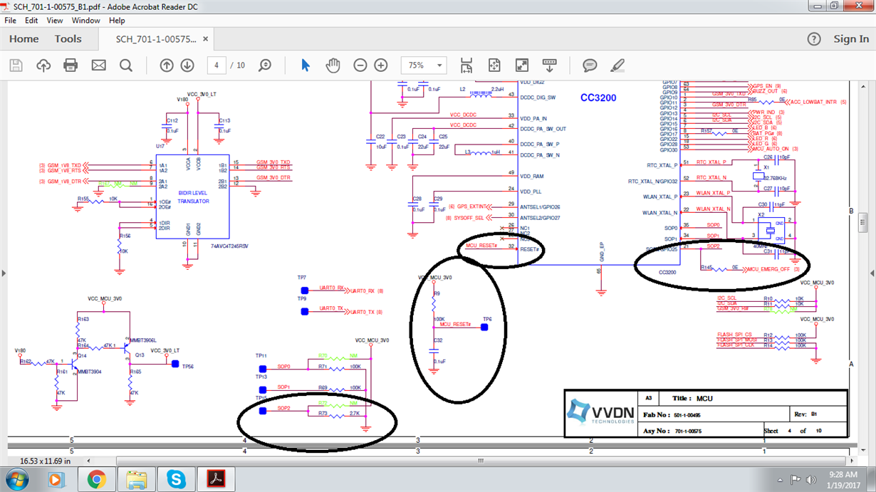
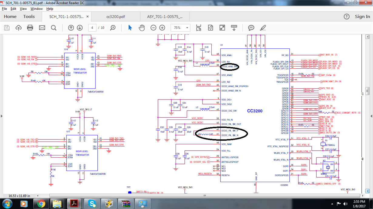
I am not able to format CC3200 by using CCS uniflash. Attaching the schematic of CC3200 which i designed.

I found CC3200 is not able to generate following voltages-

  1. Voltage on VDD_ANA1 -  which should be around 1.9V
  2. Voltage on VDD_DIG1 - which should be around 1.2V
  3.  Even i am not getting any switching DCDC_PA_SW_P and DCDC_PA_SW_N.
  4. On further investigation i found Pin No. 38 (DCDC_ANA_SW) has very low impedance around 97ohm. Can i know the possible root cause of damaging of pin no. 38 pin?
  • Hi Sagar,

    The screen shot doesn't show the full schematic. Do you have the required capacitors on the VIN pins (37,39,44, 10, 54)?

    Secondly, how are you trying to program it? 

    Regards,

    Charles O

  • Hi Charles,

    Thanks for quick reply.

    We are using CCS uniflash for programming.  We are able to program other boards but in few boards we found pin#38 has very low impedance. Can i know the possible root cause which create low impedance on Pin#38.

  • Hi Sagar,

    There is no obvious root cause for this, we will have to do some troubleshooting.

    The schematic looks good. If you have already followed the layout guidelines, the most common root cause is soldering issues.

    Do you have multiple boards? Are some of the boards working?

    When you plug in the part does it show up on the COM ports when you go to device management?

    If it showing up, when you try programming using uniflash what error/warning shows up? 

    Regards,

    Charles O

  • Hi Charles,

    Yes some boards are working. About 10 boards are not working in which i investigated following voltages is not generated(mentioned in previous mail) by MCU.

    Thats why i concluded this is the main issue. So i want to know what will be the root causes for not generating voltages and PIN38 having very low impedance on all faulty boards.

    Attached the image of uniflash.

  • Hi Sagar,

    I took another look at your schematic and found some mistakes that is most likely causing the problem.  As shown below, the converters are not well setup. Please have this amended and your board should work fine.

    It might be helpful send in the corrected schematic for review before building the boards.

    Regards,

    Charles O

  • Hi Charles,

    In Schematic same nets are short with each other. as you can see LDO_IN1 ,LDO_IN2, VDD_ANA1 and  ANS_SW_OUT pins have same net name which is LDO.

    And same for VDD_PA_IN and DCDC_PA_OUT pins have same net name which is VCC_DCDC

    We follow the same designed which you recommended in attached image.

    1 more query-

    In recent new boards,  we are able to get following voltages, but still not able to format CC3200. 

    Voltage on VDD_ANA1 should be around 1.9V
    Voltage on VDD_DIG1 should be around 1.2V
    Voltage on VDD_ANA2 should be around 3.3V 

  • Hi Sagar,

    The next plausible issues are:
    The reset. I see you don't have the RC on the reset pin, are you meeting the reset timing requirement of 100ms?
    Also SOP2 requires a 2.7k pull down resistor that is not shown on your schematic. Do you have this pull down off the page?
    lastly can you confirm all the the boards are properly soldered?

    Regards,
    Charles O

  • Hi Charles, 

    Please find the schematic we meet all of the requirements. We used 10ms reset instead of 100ms which is mentioned in CC3220 datasheet- 

    Hold the RESET pin low while the supplies are ramping up. TI recommends using a simple RC circuit (100K || 0.1 μF, RC = 10 ms).

    My doubt is over only few boards around 100 boards are proper working. But few boards are misbehave in which there is low impedance on pin# 38.  Can i know possible root cause which can damage only pin#38. I removed the CC3200 IC from board and check impedance on pin#38 and we found it is around 92E which is very low. So we concluded CC3200 IC got damage but not able to find out possible root cause of it.  We found same issue in around 10-15 boards. I did not found any issue in soldering 

    Even in few boards every thing is fine.

    40MHZ and 32.78KHz clk are coming.

    Voltages generating by CC3200's  internal LDO are fine and still not able to program.

  • Hi Sagar,

    Sorry for the delayed response.
    Can you send me your PCB layout via private message? you will need to add me as a friend first.

    Regards
    Charles O
  • Hi Charles,

    Sorry to disturb you again.

    I observed in some boards SOP2 is permanently high(3V) despite it is pull down in our schematic. can i know the reason behind this? In those boars we are not able to format the cc3200 by using CCS Uniflash.

  • Hi,

    The SOP2 pin is used for Sense On Power during boot up and as an external TCXO enable after boot up. As a TXCO enable, the pin is an output after power up and driven logic high.
    Did you check the state of the pin during startup?

    Where you able to program flash the boards a few times before the issue began? Is the SOP pin driven high by a host or connected directly to VCC? If connecting to VCC please add a current limiting resistor to prevent damaging the SOP pin.

    Regards,
    Charles O
  • Thanks Charles for reply,

    I found root cause of this. GPIO2 was shorted with VCC within MCU internally.

    Still i am facing lot of issue regarding shorting on C15 connected on LDO net. Not able to find what was the root case of it since there are other capacitors of same value are present on same net. Other capacitors ref des in schematic are- C19 and C14. But only C15 gotta damages every time.

    If i will get root cause then i can correct in new revision

  • Hi,

    What is the capacitor part number? is the same specs with that in the launchpad BOM?

    Regards.
    Charles O
  • Cap part no. and specs are -

    0201X104K100CT - Cap, Cer-X5R, 0.1uF, 10V, 10%, 0201
  • H Sagar,

    The cap meets the specs. I looked through the schematic and layout again and I don't see any reason why you C15 should get damaged. However like i mentioned earlier the stack-up is not in accordance with the recommendation and this might be part of the problem. please look into redoing the layout.

    Regards,
    Charles O