This thread has been locked.

If you have a related question, please click the "Ask a related question" button in the top right corner. The newly created question will be automatically linked to this question.

Program custom CC3200 board from CC3200 Launchpad

Other Parts Discussed in Thread: CC3200, UNIFLASH

Hi,

I want to program my CC3200 Custom board from CC3200 Launchpad.

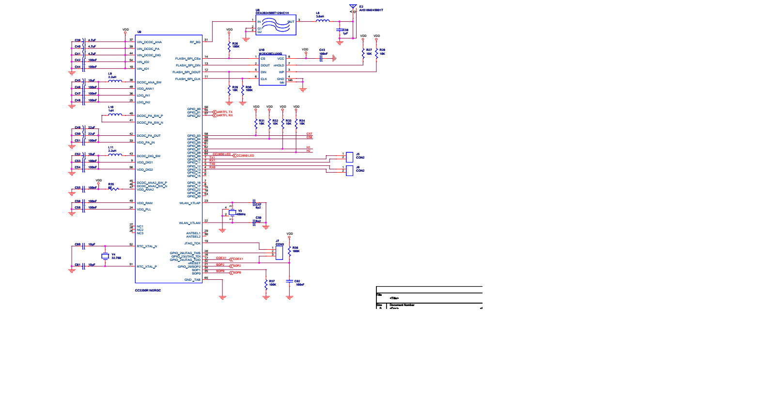
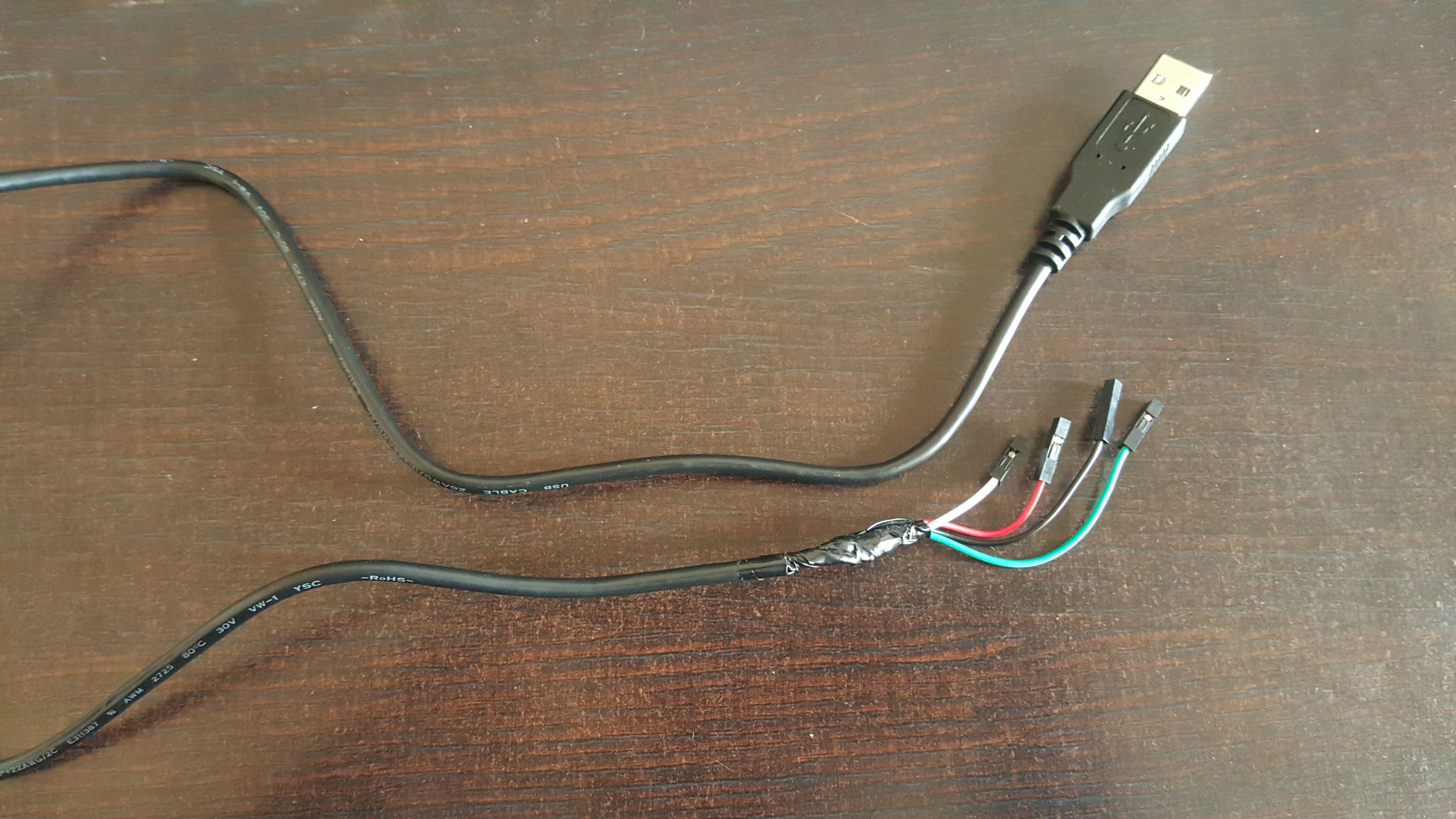
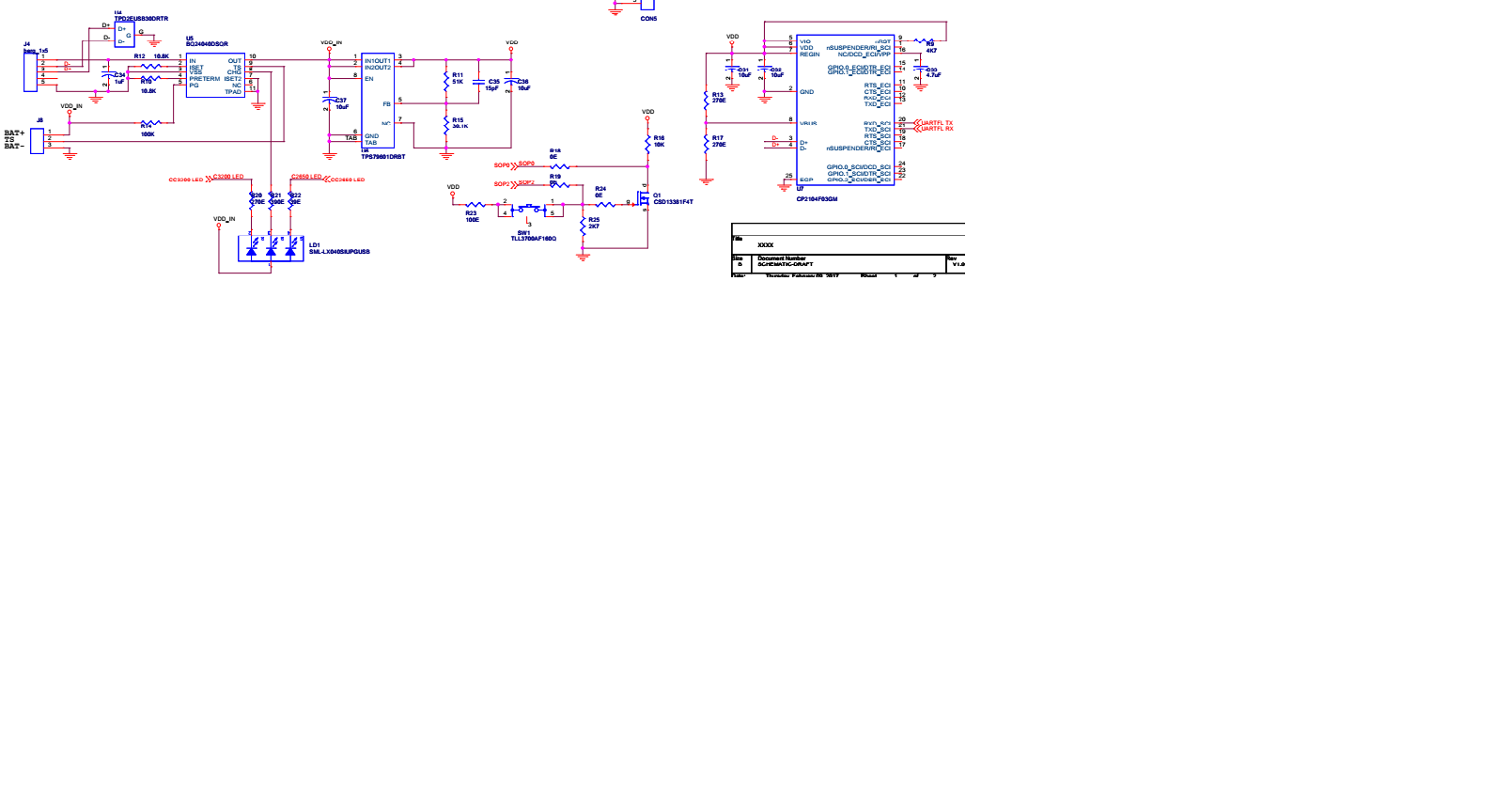
In my custom board,I have TCk,TMS,nreset,VCC and Gnd pin. I connected those pins to CC3200 launchpad but unable to program it.I'm using CCS uniflash software to program.

I got ACK signal Failed error.

Please let me know,how can I program it from CC3200 launchpad.

Thanks & Regards,

Shashank

  • Hi Shashank,

    Uniflash communicates with the target using UART. You'll need to connect those pins as well, and ensure the target is in bootloader mode using the SOP pins.

    ~roger
  • Hi Roger,

    Can I use any of uart instead of pin 55 and pin 57.

    I'm using SOP in 0 mode i.e 2W SWD mode.

    Regards,
    Shashank
  • Hi Shashank,

    No. Pins 55 and 57 are mandatory.

    To enter bootloader mode you need close SOP2 pin and reset device.

    Jan
  • Hi Roger,

    I referred the schematic from BLE-WiFI IOT gateway for my custom board. In schematic, TCK, TMS, nreset , VDD,GND is using. But I'm not aware how to program the hardware.

    Please let me know.

    Thanks & regards,
    Shashank
  • Hi Shashank,

    If you want upload firmware into CC3200 serial flash (firmware which persist restart), you need use Uniflash software. This is done in bottlaoder mode via UART (pins 55 and 57). BLE-WiFI IOT gateway design for this purpose contain USB to serial converter.

    For development purpose with CC3200 can be used JTAG/SWD. But firmware uploaded by JTAG/SWD does not persist after reset.

    Jan

  • Hi Jan,
    That means I have to connect only TCK,TMS,VCC,GND pin to launchpad and sop2 should be connected.Am I Right?

    Thanks & Regards,
    Shashank
  • Hi Shashank,

    - For development-debugging you need connect JTAG pins, GND, VCC and set SOP configuration for you debug mode (JTAG/SWD)
    - For programming by Uniflash you need connect UART (55, 57), GND, VCC, reset and SOP2 pin.

    Jan
  • Hi Jan,

    For Development-debugging I have connected TCK pin to CC3200 LP and TMS pin to CC3200 LP as well as vcc and GND. I 'm confused where I connect nreset pin of my custom board in Launchpad?

    Please let me know

    Thanks & Regards,
    Shashank
  • Hi Shashank,

    For debug is not necessary connect reset pin.

    Jan
  •   Hi Jan,

    Attached is the schematic images for my custom board for CC3200.Please have a look at help me to program my board using uniflash software.

    I have CC3200 Launchpad as well as smart RF06 board.

    Please guide me .

    Thanks & Regards,

    Shashank

  • Hello Shashank,

    Procedure here to flash should be :-

    1. Power Up board and connect USB.  USB->UART should enumerate as COM port.

    2. Start Uniflash, configured for CC32xx serial connection and set the appropriate COM port.

    3. Start a 'Format Operation'.  Console will prompt to 'Reset Target'

    4.  When prompt is seen, hold down SW1 (which should set SOP2=1, and SOP0=0, for UART load mode), and while SW1 is pressed, assert a low pulse on the RESET line (J7, pin 3) to latch the SOP pins and start UART loading mode.

    5. Uniflash should continue to FORMAT the device.

    6.  After that, you can program a service pack, etc.

    [ If this doesn't work, please check that the SOP pins are being set correctly by the SW1 logic, and that the reset signal is good, and check that the USB->UART is working with a terminal program, by potentially looping back  UARTFL_TX/RX ].

    Hope that helps,

    ~roger

  • Hi Shashank,

    Please see www.ti.com/.../tidua62 at chapter 5.1.1, 5.1.2, 5.1.3.

    But generally when you need put CC3200 into bootlaoder mode for flashing by Uniflash, you need do this:
    - connect UART to PC (by USB->Serial converter, etc)
    - set SOP2 to high
    - reset CC3200 by reset pin (pulse at reset to low)

    Jan
  •  Hi Roger,

    Thanks for the procedure but here Com port is not displayed on my device manager.

    Also, In my hardware instead of USB Port I have berg strip  as tagged as J4 connector (as referenced with above schematic).

    Currently,I'm using Usb cable in that 1 end is having usb port and other end is having female jumper which I attached to J4.Attached is the image.

    Thanks & Regards,

    Shashank

  • Hi Jan,

    I tried the same appproach as roger mentioned.But i unable to see my com port in device manager.What's going wrong ?


    Thanks & Regards,
    Shashank
  • Hi Roger,

    Now I'm able to see com port in device manager but when i'm going to program uniflash shows below error -

    19:59:51] Begin Program operation.
    [19:59:52] INFO: > Executing Operation: Connect
    [19:59:54] INFO: setting break signal
    [19:59:55] INFO: detecting FTDI for device reset
    [19:59:55] ERROR: No device USB ports were found
    [19:59:55] INFO: --- please restart the device ---
    [20:00:10] ERROR: ---reading ACK signal failed---
    [20:00:10] WARNING: ---seting break signal to false failed---
    [20:00:12] INFO: setting break signal
    [20:00:13] INFO: detecting FTDI for device reset
    [20:00:13] ERROR: No device USB ports were found
    [20:00:13] INFO: --- please restart the device ---
    [20:00:28] ERROR: ---reading ACK signal failed---

    But COM Port is displayed in Device Manager.

    I pressed the SW1 switch and toggle the reset line(J7,pin3) but unable to program it.

    Currently, In my board reset switch is not present.Please have a look on schematic for SOP.

    Please help to overcome this issue.

    Thanks & Regards,

    Shashank

  • Hi Roger & Jan,

    Thank you for the response.My issue is resolved now. :)

    Best Regards,
    Shashank