This thread has been locked.

If you have a related question, please click the "Ask a related question" button in the top right corner. The newly created question will be automatically linked to this question.

Linux/WL1837MOD: Why can IRQ line stay high on boot?

Part Number: WL1837MOD
Other Parts Discussed in Thread: TXS0108E, AM3359

Tool/software: Linux

Once again trying to get a custom module with WL1837MOD working, now that the new hardware came in.

I am using BeagleBone Black as the reference platform.  We took a board we designed previously for testing which was able to operate properly at reduced MMC clock speed.  The main difference between the new board and the one we were able to make work is in the voltage regulators (for 3.3V and 1.8V).  The previous design has onboard regulators similar to TI reference designs, whereas the new board is relying on off-board regulators...in fact both the 3.3V and the 1.8V supplies for the WL1837MOD are coming straight off the TPS65217C in the new design (LS2_OUT and LS1_OUT, respectively).

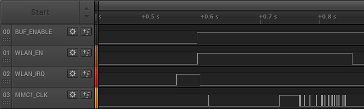
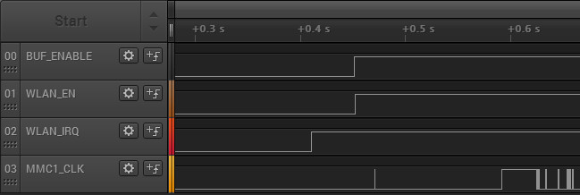
I have verified the BUF_ENABLE and WLAN_EN are matching the same startup sequence for both the reference board (the element14 WiFi cape) and our new board.  However, on the working reference board, the WLAN_IRQ signal goes low about 19ms after the WLAN_EN goes high.  But on our board, the WLAN_IRQ stays high indefinitely.

It seems like the WLAN_IRQ goes low on its own...that it doesn't require any MMC/SDIO transactions to make it go low initially.  What could cause the WLAN_IRQ to stay high on initial power up?

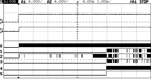
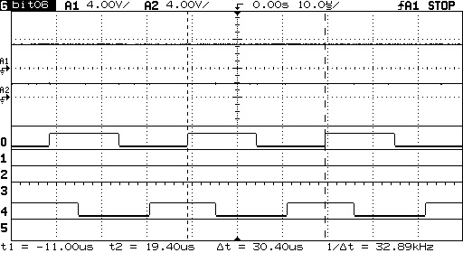
Working Reference Board:
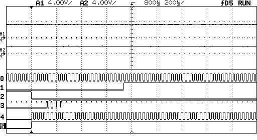
Failing Board:

  • FYI, today I hacked in the discrete regulators from the previous design. They are measuring good voltage at the new module, but we still have the same WLAN_IRQ signal stuck high after WLAN_EN is enabled. So I don't believe it's simply a voltage regulation issue.
  • David , Are you booting WiLink8MOD in debug mode or operational mode ? Pls check 'sense on reset' section of www.ti.com/.../swru437.pdf . WLAN_IRQ should be low before WLAN_EN is asserted for it to boot in operational mode.

    Saurabh
  • Hi David,

    Lets ensure that you have the proper start up sequence. In the new design is VBAT and VIO up and stable before WLAN_EN is asserted? Also is the slow clock on and stable? this is a requirement.

    I suggest you add the VBAT, VIO and slow clock to the plots above. This will be telling as to what is going on with WLAN_IRQ.

    The proper sequence is shown on page 22 of the datasheet (figure 5-2). This timing needs to be validated to ensure proper startup.

    My guess is that it is related to timing as the reference works, but modifying the supplies causes an issue on the new design. Also I would check to ensure that new supplies from a current point of view are sized appropriately.

    I hope this helps.

    Thanks,
    Riz
  • You guys are making me get out the big scope :).  I will get the requested additional IO lines captured tomorrow, and compare again against the power up sequencing which I have already reviewed.

    We are only attempting to use normal operating mode.  We are relying on the indicated internal pullup/pulldown resistors (within the WL1837MOD) to enter this mode.  My understanding is normal operating mode is not dependent on the WLAN_EN control, but rather the power-up state which should be the default since the level translator should be disabled initially (I will check on this point also tomorrow morning, but it's the same BBB driving the same line on both boards).

    As you can see, the "working" board also has the WLAN_IRQ HIGH when WLAN_EN is enabled, as in the BBB + Element14 reference design.  Note that in the e14 design, the WLAN_IRQ is set high prior to enabling the level shifters due to the internal pullup in the CPU side (I am measuring the 3.3V side of the level shifter).  I'm not sure if there's a good point to measure the 1.8V side of the WLAN_IRQ (I don't have layout files for the e14 board).  This line was high on our board on the 1.8V side, even with the level translator disabled, and we have no external pullup on the 1.8V side.

  • I have taken some captures from the board with the add-on voltage regulators (these regulators are the same as used in the reference design, TPS73618DBVR and TL1936A-33DCYR).

    The screen grabs are a bit archaic, but here is the signal key:
    A1 - 3.3V (VBAT)
    A2 - 1.8V (VIO)
    0 - SLOW_CLK
    1 - WLAN_EN
    2 - SDIO_CLK
    3 - WLAN_IRQ
    4 - BT_AUD_OUT
    5 - BUF_ENABLE
    The digital signals are all taken from the 1.8V side of the level translator.
    I cannot tap the BT_UART_DBG pin...this is not connected on our board.

    Some measurements that are difficult to show:
    Time between 3.3V and 1.8V up: ~55ms.
    SLOW_CLK is on as soon as 1.8V supply is up.
    SDIO_CLK is HIGH as soon as 1.8V supply is up (there are 10K pullup resistors on the SDIO bus lines on the 1.8V side).
    Time between BUF_ENABLE and WLAN_EN high: ~736us.

    SLOW_CLK frequency is about 32.8 kHz.  The part used is Abracon ASEK-32.768KHz-LRT.

    It seems the BT_AUD_OUT is oscillating from the BBB side. In the e14 reference design, they are using that signal for the slow clock. Could that be interfering with the bootup mode in this case?  I could disable this in the BBB DTS (but my platform does not do this).

    It also appears my digital probes (WLAN_EN and WLAN_IRQ) are picking up noise from other probes.  I could tap these with the analog probes if it would be helpful.

    Initial Power Up, from VBAT high through initial sequence:

    Closeup of VBAT to VIO:

    Closeup of SLOW_CLK:

    Closeup when BUF_ENABLE is activated:

  • Based on the HW integration guide, it seems the BT_AUD_OUT and WLAN_IRQ should be LOW whenever the WLAN_EN is first asserted. Perhaps this is caused by the BT_AUD_OUT...I will see if I can disable the clock output on that IO and see if it makes a difference.
  • I disconnected the BT_AUD_OUT from the CPU side to rule it out. No change. Any other ideas?
  • I noticed the only difference between the 2 startup modes (normal and debug) is the WL_IRQ pin...whether it is pulled up or not. I think it shouldn't matter the pullup state on the IRQ...the WL1837MOD should start up either way, assuming the BT_AUD_OUT and BT_UART_DBG are also in the proper states.

    It seems the working reference board I have has a 10K pullup on the WLAN_IRQ on the 1.8V side. I can see if I can install a 10K resistor on our board (we have a pad for it, just marked it do not populate).
  • David,
    For WiLink8 to boot up in operational mode WLAN_IRQ level should be low - "IRQ_WL = 0, UART_DBG_BT = 1, AUD_OUT_BT = 0" . 10k pull up on WLAN_IRQ will be needed in case you want it to boot in debug mode.
    For power up/down sequence pls check section 5.21.2 of www.ti.com/.../wl1837mod.pdf. Make sure VBAT,VIO and slow clock are stable before WLAN_EN is asserted
    Is BT_EN low at all times ? What issue do you see if failing scenario ? You mentioned you had to reduce SDIO clk to get it working on functional board - can you please explain why you had to reduce SDIO clk

    Saurabh
  • Does it matter if it boots up in debug or in operational? Shouldn't the SDIO interface respond the same either way?

    Can you see the traces I captured? The VIO, VBAT, and SLOW_CLK are clearly stable before WLAN_EN is asserted.

    BT_EN is actually high before the buffer is enabled and never set low. This is exactly the same as the working element14 reference board (Wireless Connectivity Cape).

    I think I've confused you on the boards. I actually have 3 boards I'm working with:
    1) Element14 Wireless Connectivity Cape + BBB -> Works fine
    2) Our own design for our own AM335x based CPU board -> Doesn't work
    3) Our own design that plugs into the BBB -> Works but with reduced MMC clock speed

    I think the issue with board (3) is related to MMC bus impedance and length matching. However, the schematics for (2) and (3) are very similar...we only made changes due to the mating connector, and changed the connection order on the TXS0108E modules for layout reasons.

    To eliminate power supply issues, I wired the power supplies from a sample of board (3) to the board (2). We made it possible to patch in the supplies in case the new supply chain on board (2) wasn't sufficient.

    I could supply the schematic for our board (2) if it would help.
  • Hi David,

    Have you been able to solve your issue yet? If you wish you can send the schematics and layout. Please note the e2e is a public forum so if there is any confidential information, please send via e-mail to rizwan.murji@ti.com. If not you can post on e2e.

    Thanks,
    riz
  • No, I have not been able to make much progress. I have just emailed you some schematics, for your reference.

    One of the boards is our own design and mates directly to the BeagleBone Black. I received a new sample of this board today and I can confirmed it is properly initializing with the CPU.

    The board we really want to get working (the smaller one), is based on the schematic as the one we have working, but we changed some discrete component values and switched to the connector we intend to use for our own base board.

    The third is just an adapter to bring the needed BBB GPIOs to the smaller board's header so we can test the small board also with BBB.

    So I ordered a COM8I module and am trying to use it to rule out any assembly issues we might have. I have wired our level shifters and power supplies to the COM8I and now I am able to detect the WL1837MOD ("unknown CIS Tuple" message is getting displayed), but the driver is hanging during intialization since the WL1837MOD IRQ is not going high. This is the same issue we've had in the past prior to changing over to the TXS0108E level shifters.
  • Sorry, correction, the system is not waiting for the IRQ pin to go high. It is simply waiting for the MMC transfer to complete, but it never does for some reason. Will be trying to get something useful from the MMC pin traces...
  • I managed to get my crazy setup working by changing the MMC bus to 1-bit mode (instead of 4-bit). Also still running at 1 MHz, but I can play with this. This implies I have some connection issue with the 4-bit MMC data bus (which wouldn't surprise me with how close I had to solder some of those pins).

    At least with this I can play around with some things, especially with trying to interface directly to our own board.
    I would like to keep this open for a short time in case you guys at TI find something of concern in the schematics. I'll keep you posted if I find anything else.
  • Hi David,

    I Am going to close this issue out. Feel free to send the schematics over email for a review, or re-open the tread if needed.

    Thanks,
    Riz
  • Hi Rizwan,

    OK, I think I figured something out...maybe.  On our own board we are using the MMC2 interface (labeled mmc3 in device tree).  On the BeagleBone, we are using MMC1 (labeled mmc2 in device tree).  What I noticed is that, when using MMC2, the DAT lines are not outputting data from the CPU when they should.  This seems to be the cause of the failure.  I have checked the mux configuration and it appears to be correct (PIN_INPUT | MUX_MODE3).  I confirmed it with devmem2 for the DAT0 pin.

    So right now, my best guess is that there's an MMC driver bug possibly in the 3.12 kernel.  We are using this interface fine with a WL1273 with the 3.2 kernel, so the interface itself should be working fine.  I have noted many other forum posts that are having problems with MMC2, and most people gave up and switched to one of the other MMC interfaces.

    I am working on bringing up the board with the 4.9 kernel and will check this DAT0 line again.  Is TI aware of any MMC bus issues with the 3.12 kernel with MMC2?  My guess is that, since none of the reference boards are using this bus much, the bug may have gotten overlooked.

    My method of testing was as follows.  I could see the data on DAT0 on the BeagleBone Black MMC1, but not on our board on MMC2 (I have the MMC bus in 1-bit mode for now).  I disconnected the DAT0 from the WL183x and confirmed the AM3359 CPU is outputting the data on the DAT0.  I disconnected the same line on our board and saw the MMC2 DAT0 is never clocking out any data.  All data transaction up to that point (on MMC_CLK and MMC_CMD) match up well between the 2 boards.

    PS, I sent our schematics for you to look at Feb 2...

  • Note also that if I switch the DAT0 pin to GPIO mode (MUX_MODE7), I can switch it high and low manually as a GPIO, so I don't think it's any electrical issue at this point.
  • Sorry, I said 3.12 kernel above. It's actually 3.14 I have been using, from the EZSDK 8.00.00.00 package.
  • Hi David,
    I believe AM335x EVM has MMC2 connected to WiLink8 and it works ok. You may use this for reference :github.com/.../am335x-evm.dts . Kernel 3.14 is old , I can't recollect if there were any specific MMC issues on that version

    Saurabh
  • Thanks for this update...this gives me a good hint.  I looked at the referenced DTS and I see some syntax has changed.  However, I'm particularly interested in the way the edma elements are defined:

    dmas = <&edma_xbar 12 0 1
                   &edma_xbar 13 0 2>;

    there are extra numbers here from what I've seen in previous notes...so perhaps this is related.  My colleagues are still updating files related to 4.9 kernel on my platform, so I haven't managed to bring it up yet.  I will try making this small change to my DTS file when I am back in my regular office next week.

  • OK, I figured it out (finally!).
    It was a DMA issue, but the above fix was only for newer kernels with a revised EDMA setup in DTS.

    With some Google searches, I ran across a site that mentioned bugs in the DTS node parsing:
    yurovsky.github.io/.../sitara-am335x-edma-fix.html

    While the suggested fix there still did not work for me, I found the kernel documentation here:
    elixir.bootlin.com/.../ti-edma.txt

    And so I changed the xbar line in my DTS from:

    &edma {
    /* Required to get DMA on HSMMC2 (mmc3) */
    ti,edma-xbar-event-map = <1 12
    2 13>;
    };

    to:

    &edma {
    /* Required to get DMA on HSMMC2 (mmc3) */
    ti,edma-xbar-event-map = /bits/ 16 <1 12
    2 13>;
    };

    And now the MMC2 bus is talking to the WL1837MOD chip.
    It seems the DTS parsing functions have issues unless we explicitly tell them this is a 16-bit array.

    Thanks for all the help! I can finally move forward!
    This gets me up and running. We may have some small review to do on newer kernel DTS entries, but we can tackle this during the migration to 4.9 and I can focus on getting this board tested and ready for production.