This thread has been locked.

If you have a related question, please click the "Ask a related question" button in the top right corner. The newly created question will be automatically linked to this question.

CC3220SF-LAUNCHXL: Custom PCB Questions

Part Number: CC3220SF-LAUNCHXL
Other Parts Discussed in Thread: CC3220SF, , UNIFLASH

Hello,

I'm currently making my way through the PCB design checklist for the CC3220SF and have run into a couple recommendations that I am not sure how to address:

1. For PA DCDC IN (Pin 39), the checklist states that 4.7 uF and 100 uF decoupling capacitors are necessary. However, on the CC3220SF-LAUNCHXL schematic there is only the 4.7uF capacitor, and I'm wondering if the 100 uF cap is necessary or what the reasoning for omitting it on the launchpad is?

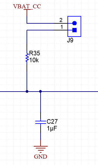
2. For the reset (Pin 32) there is an RC circuit recommended by the checklist, and this checklist is reflected by the schematic for the launchpad. However, the resistor in that circuit is only connected to VBAT via jumper J9, and in my testing I've never had that jumper bridged, thus the resistor has no effect on the reset. I have thus omitted that resistor on my board since, but I'm wondering if this is acceptable? I have the reset pin connected to both the UART interface for programming via UNIFLASH and the JTAG header for debugging on my board. Given that there is no resistor in how these connections are wired on the launchpad, I'm assuming this will work similarly. 

3. I have both the UART tx and rx connections (Pins 55 and 57, respectively) connected to 100kohm pull ups per the checklist, but these pull ups are not present on the launchpad from what I've seen, is there a reason for this? Is it possible they'll simply be on the debugger?

4. The checklist states that external pull ups are recommended for all GPIO. If a GPIO pin is unused and I have no interest in its behavior, can I simply leave it not connected, or should it still have an external pull up/pull down resistor? Furthermore, the checklist states that the pull ups/downs are necessary to maintain the state of a pin, but how is this possible if the pin is meant to be high before a reset and there is a pull down connected to it?

5. Lastly, I hardwired the SOP headers as such (SOP: 010) to default to the UARTLOAD_FUNCTIONAL_4WJ. According to the documentation for this mode, it should allow me to setup the board via UART after manufacture and load my software into external flash. However, the checklist consistently states that UARTLOAD mode should be used. Has anyone substituted UARTLOAD_FUNCTIONAL_4WJ for UARTLOAD successfully in a similar use case? Are there any unforeseen issues? I'm fairly confident given the documentation but wanted to double check.

I will be using the XDS110 from the CC3220SF-LAUNCHXL to load the software via UART and UNIFLASH onto the custom board. Please let me know if you need me to clarify or provide any further information. Any info is greatly appreciated!

  • Hi CHristian,

    The 100 uF decoupling caps I think are on another page. We'll get back on the other items.

    -Aaron
  • Hi Christian,

    Christian Ouellette28 said:
    I'm wondering if the 100 uF cap is necessary or what the reasoning for omitting it on the launchpad is?

    the two 100uF caps are bulk capacitors recommended if the battery cannot source the peak currents. it is in the power management section of the schematic on page 5.

    Christian Ouellette28 said:
    the resistor in that circuit is only connected to VBAT via jumper J9, and in my testing I've never had that jumper bridged, thus the resistor has no effect on the reset. I have thus omitted that resistor on my board since, but I'm wondering if this is acceptable?

    There is a reset timing requirement (section 4.14.1 of the datasheet). The RC circuit ensure this timing is met.

    Christian Ouellette28 said:
    I have both the UART tx and rx connections (Pins 55 and 57, respectively) connected to 100kohm pull ups per the checklist, but these pull ups are not present on the launchpad from what I've seen, is there a reason for this? Is it possible they'll simply be on the debugger?

    I believe this is to maintain the states of the pin and prevent it from floating at any time.

    Christian Ouellette28 said:
    The checklist states that external pull ups are recommended for all GPIO. If a GPIO pin is unused and I have no interest in its behavior, can I simply leave it not connected, or should it still have an external pull up/pull down resistor? Furthermore, the checklist states that the pull ups/downs are necessary to maintain the state of a pin, but how is this possible if the pin is meant to be high before a reset and there is a pull down connected to it?

    You can leave unused GPIOs as NC if it has not effect on your application. According to the checklist  "All the I/O pins will float while in Hibernate and Reset states. Please ensure pull-ups/pull-downs are available on board to maintain the state of the I/O"

    Christian Ouellette28 said:
    5. Lastly, I hardwired the SOP headers as such (SOP: 010) to default to the UARTLOAD_FUNCTIONAL_4WJ. According to the documentation for this mode, it should allow me to setup the board via UART after manufacture and load my software into external flash. However, the checklist consistently states that UARTLOAD mode should be used. Has anyone substituted UARTLOAD_FUNCTIONAL_4WJ for UARTLOAD successfully in a similar use case? Are there any unforeseen issues? I'm fairly confident given the documentation but wanted to double check.

    If SOP pins are hardwired to a  default state then  you don't have acess to the other boot modes. It is advisable to avoid doing this or at least add test points and DNPs to provide the option just in case.

    Regards,

    Charles O

  • Hi Charles,

    Thanks so much for the reply. I've made several changes based on your feedback. The only thing I'm still unsure about is that RC circuit attached to the reset pin. I understand what you're saying, but I looked through the design files and found that the resistor would only be active if that jumper is attached. Given that I have never attached that jumper (J9) in my testing and debugging on the launchpad, would it be safe to assume that I could omit that resistor on my board given that the jumper essentially "omits" it electrically on the launchpad? I would certainly still include the capacitors as those are no impacted by the inclusion or omission of the jumper.

    Thank you!
  • Meeting the reset timing is required. You can leave out the resistor if you can ensure the "host" toggling the reset pin meets the required timing.
    I recommended having it placed.

    Is there any specific reason why you want to leave this out? its just one more component on the bom.

    Regards,
    Charles O
  • I'm only omitting it because I'm not going to place the header that's on the launchpad (J9) on my board, so there's no point in placing the resistor. I have nothing against actually including it but I feel like it won't be functional. I have the reset pin on the MCU tied to both the UART header for use with UNIFLASH and the JTAG header, so those should both be able to reset the board as well. Worst case, I think I could simply use an external resistor tied to the UART+reset header to toggle the pin manually should the need arise.

  • For reference, C27 is placed as normal, but the resistor (R35) and header (J9) are not on my board. However the reset wire (horizontal center in this pic) is connected to an external header to be used in conjunction with UART as well as connected to a JTAG header. 

    UPDATE: Just tested the launchpad with the pull-up jumper installed and both the uniflash and JTAG programming worked as usual (I thought the pullup would interfere) so I'll just include it on my board given that there seems to be no reason not to and to avoid potential problems. Sorry for the confusion!