This thread has been locked.

If you have a related question, please click the "Ask a related question" button in the top right corner. The newly created question will be automatically linked to this question.

CC3220: CC3220SF power consumption details

Part Number: CC3220

Hi CC3220 champs,

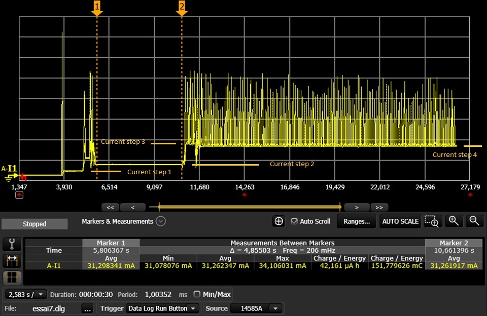
We performed a first current measure on the CC3220SF LP using the out of box example – and we were surprised to see consumption peaks which are much above 25mA as we could expect from the datasheet just after boot time.

The first peak for instance we can see in the attached power analyzer snapshot is about 450mA which sounds to correspond to a peak calibration current.

By performing such measurements we like to understand and define the max instantaneous current (not average) which is consumed during boot time until first line of code execution since the current source which is used for the first 4 minutes after boot time is very limited.

Questions :

Q1 : What are the here below current big peaks correspond to (the ones above 200mA)? Specially the first one above 450mA? Is it expected?

Q2 : What the different current steps (1/2/3/4) here below correspond to?

Q3 : Could you share any use case current consumption figures like commissioning, pairing, …. For the CC3220SF? Any additional information versus Datasheet about consumption is welcome. As you understand, the power consumption evaluation is key in this application

Q4 : When calibration happens in practice (I read the DS no need to copy/paste)? What frequency? Is it just about boot up and then when temperature varies?

Thank you!

Best regards,

Guillaume

  • Hi Guillaume,

    To answer your questions:

    1. The current spike at the start of execution corresponds to antenna calibration.

    2. Current step 1 likely corresponds to initializing all of the IOs. Current step 2 corresponds to starting the network processor (NWP) with sl_start(). Current step 3 + 4 correspond to the NWP entering into an active TX state and sending data.

    3. A good guide for power consumption in different cases is the power management application report:
    www.ti.com/.../swra502a.pdf
    The guide goes into more detail than the datasheet and covers different test cases that illustrate typical applications and the expected current consumption.
    For example, the pairing current can be deduced from the "intermittently connected" test case, where the CC3220 connects to an AP and sends a packet of data before going to sleep. The power consumption measurements in that report are based off of the power_measurement example in the SDK. By running that example, you can replicate the measurements observed to determine how much current is consumed in each case of interest. Furthermore, you can modify that example to change parameters such as time spent asleep, data sent per wakeup, etc. to suit your application.

    4. There are actually a couple possibilities for how often calibration is done, depending on the calibration mode setting programmed onto the flash. The different modes can be found in Table 3-9 (page 68) of the NWP programmer's guide:
    www.ti.com/.../swru455e.pdf

    In the default "normal" profile, calibration will occur upon every reset, as well when there is a change in temperature >20C since last calibration. Other than those two conditions, calibration data will be kept indefinitely. Setting the mode to "triggered" will remove the reset calibration.

    Regards,
    Michael
  • Hello Michael,

    Thank you for this excellent support and answers.

    About peak current : I performed additional current measurements using the power_measurement_CC3220SF_LAUNCHXL_no_rtos example and as you can see in the snapshot here below the current peak is "only" 92mA (instead of 450mA seen with the previous example) at boot up before stabilizing at 25mA (basic code running)

    I suppose that such peak current does not correspond to a radio calibration (and then such code example implements the radio calibration "triggered mode").

    Where does this peak current come from? IO init? Could such peak current be avoided?

    Thank you!

    Best regards,

    Guillaume

  • Hi Guillaume,

    The radio calibration modes are set through Uniflash, and are not set through the application code. Thus, your code might still be running in normal mode and calibrating every reset. Try setting the calibration mode setting in Uniflash under Device->Radio Settings->PHY Calibration Mode to onetime and then reflashing the device and seeing if you get the same results.

    If changing the calibration mode to onetime results in the same behavior, then I'm not sure what the current peaks could correspond to beyond general processor initialization. Normally a current spike in that range would be a radio rx/tx, but that doesn't make much sense given that the NWP isn't even initialized at this point. Most likely, it is something that cannot be changed.

    Regards,
    Michael