This thread has been locked.

If you have a related question, please click the "Ask a related question" button in the top right corner. The newly created question will be automatically linked to this question.

LAUNCHCC3220MODASF: Possible I2C Clock Stretching?

Part Number: LAUNCHCC3220MODASF
Other Parts Discussed in Thread: CC3200

Hello,

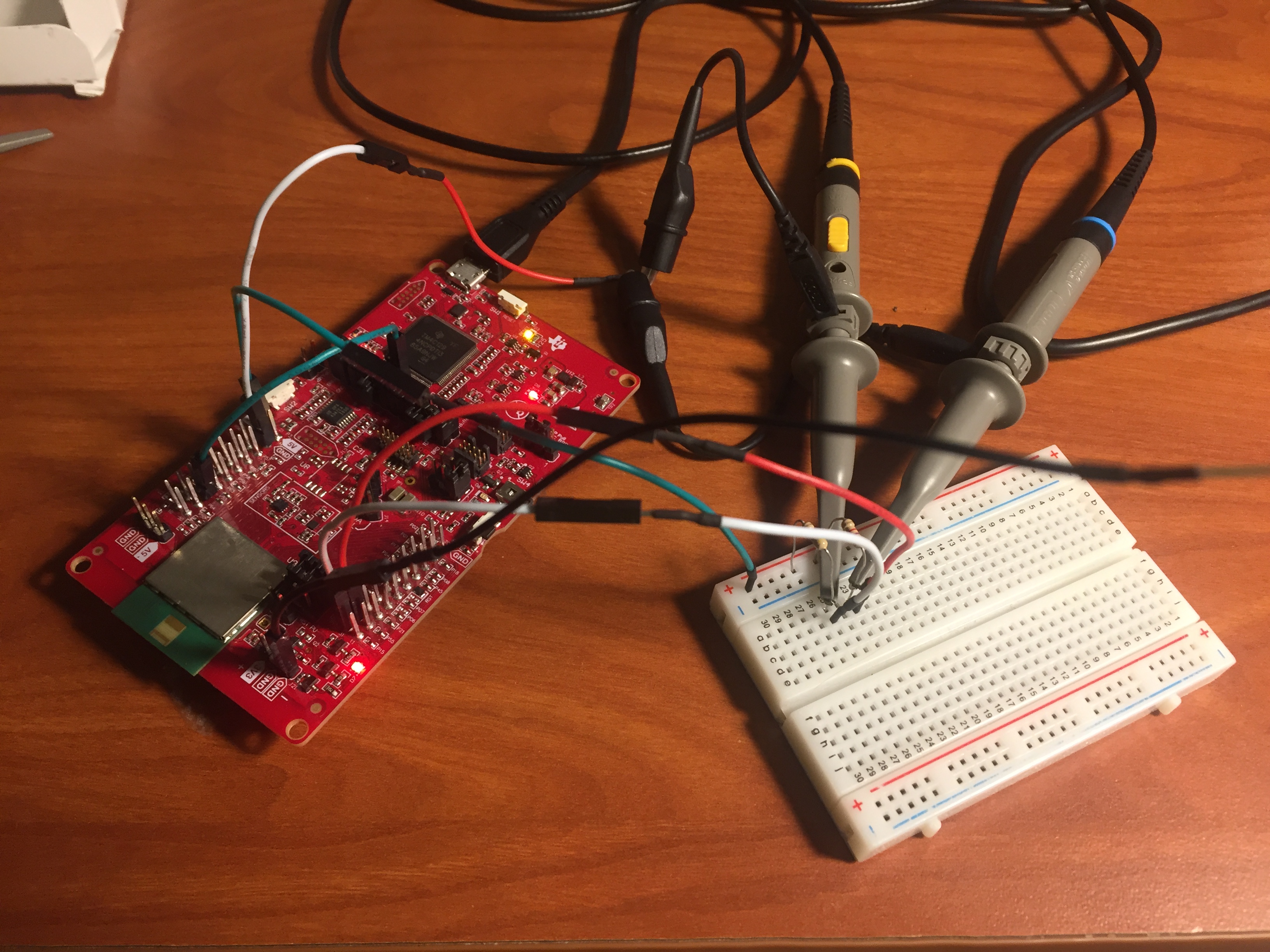
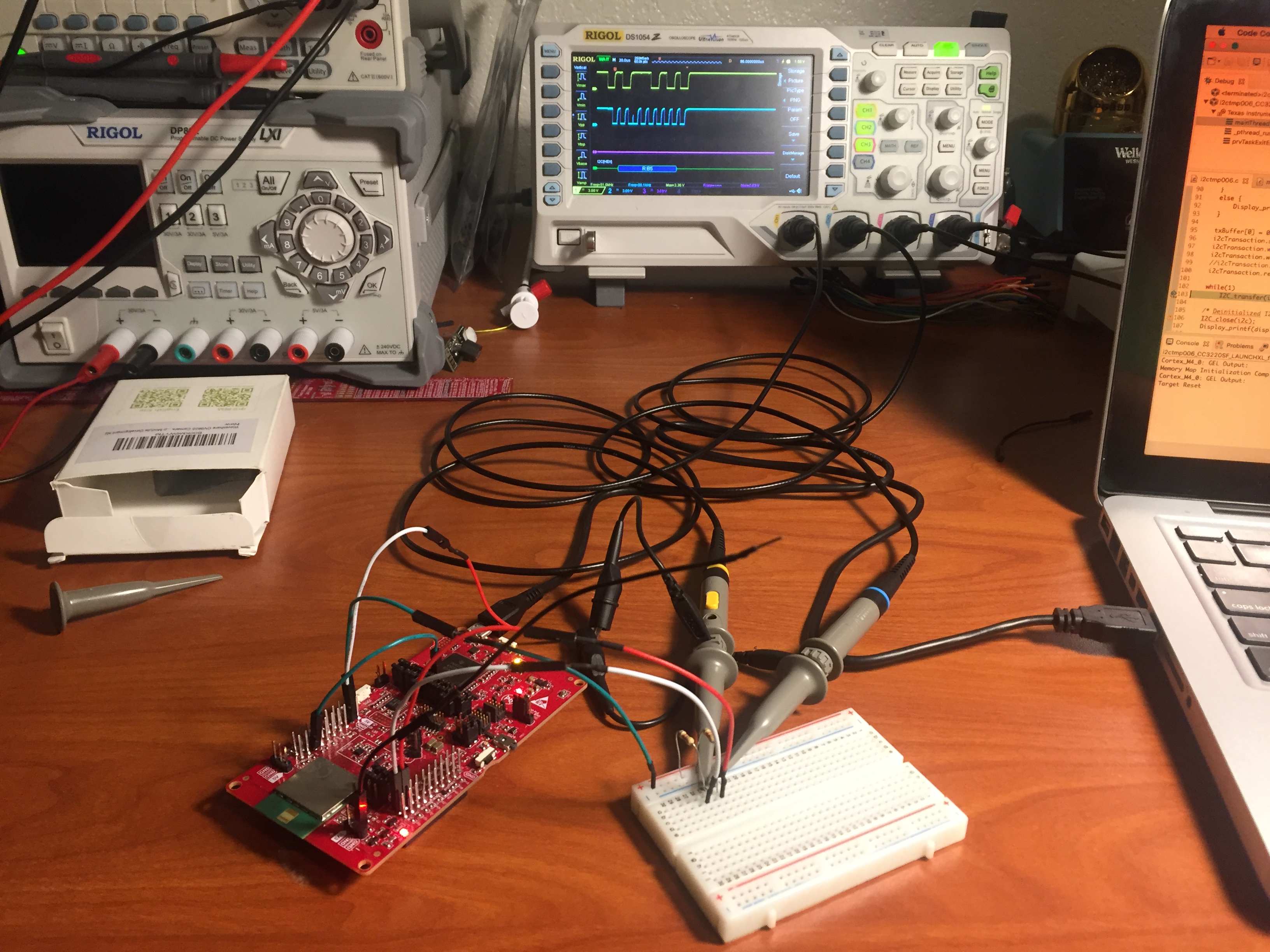
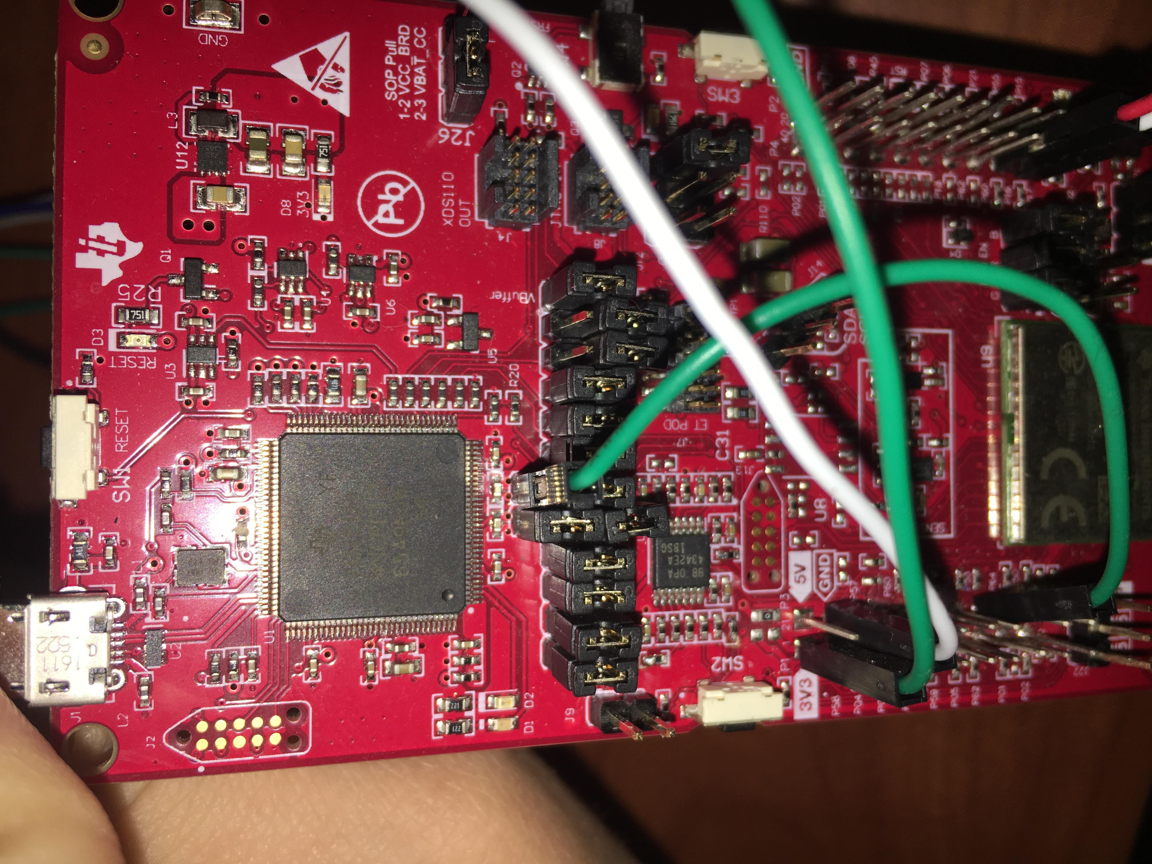
I have been working with the CC3220MODASF module for a while now and I have not been able to get an appropriate I2C transaction due to what appears to be clock stretching. I am trying to replicate the CameraBooster pack design that was released for the previous version of the module, the CC3200. Here is the datasheet for the MT9D111 camera module that I am working with. Attached are two pictures, the first picture is the clock when the physical 6MHz clock going to the camera module is being generated by the CC3220 and then the second picture is when the clock used is coming from an external 6MHz source.

We have the CC3220's I2C set to be 100kHz as can be clearly seen from the oscilloscope screenshots.

Any quick insight into this behaviour would be appreciated. I have been struggling with this issue for a few months with a number of different camera modules.

  • Shane - 

    the device supports clock stretching when slave requests it - see  section 7.3.10, page 215 and on for the register settings on the timer for this. 

    According to this data sheet -  

    (page 180) - the camera module is the slave, and therefore responsible for "requesting" the clock stretching. So the above (for the CC3220, acting as the master) will help you adjust the timer value needed to support this module. 


  • Hi Josh,

    Thank you for your quick reply! I will give this a shot. Do you have any insight into why this issue may be happening when the camera module is sourcing its 6MHz clock from the CC3220, but it doesn't happen when the clock is coming from an external function generator?

    If it was indeed only a clock stretching issue I would have expected to see it in both cases.

    Shane
  • Shane -
    the basic way clock stretching works is an interaction between the slave and the master, not with an interjected signal.
    Did you catch the slave holding the clock down (which is basically a request for stretching)

    www.i2c-bus.org/.../
  • Josh,

    Yes, I understand that clock stretching is a form of interaction between the slave and the master. I'm concerned with 'why' there is clock stretching when the camera module and the CC3220 are communicating while the camera module is being clocked by the CC3220's 6MHz clock (this is not the 100kHz I2C clock) but there is no clock stretching when the camera module has an external 6MHz clock driving it...

    This is of great concern to me. Why does I2C communication not have any clock stretching issues when the camera is being externally clocked but then the I2C starts to have issues when clocked directly from the CC3220. My original pictures are still very useful in describing the issue that I'm trying to describe.
  • Josh,

    I've continued looking into this issue.  Attached you will see pictures describing my bench top test setup using the CC3220 LaunchPad and a screenshot of the I2C lines coming from the CC3220.  Notice that there are no slave devices connected to the CC3220 which is acting as a master. The on-board I2C devices have their jumpers for SDA and SCL disconnected.

    The project that is running is the example project known as 'i2ctemp006' that TI provides.

    This is very concerning. It appears as though a scenario that looks like a clock stretching situation is occurring even when there are no slave devices connected to the master and when running the provided sample code. 

    I have also tried your suggestion of working with the I2C timing register, even when that value is set to its highest possible value this issue occurs.

    Your hasty response is much appreciated.

    Shane

  • Shane - 

    i can see you are using pins that are normally used for JTAG, and it looks like the XDS110 is still connected. 

    this means you modified the board by moving resistors and changed the code, too. any chance you can check with the default code and default pins for I2C? 

    and/or remove the jumpers which connect the CC3220 pins to the XDS110 (P16_GPIO_23 = P16_JTAG_TDI = XDS_JTAG_TDI, P17_GPIO_24 = P17_JTAG_TDO = XDS_JTAG_TDO)

    see ==>

  • Hi Josh,

    It's hard to tell from the pictures that I previously sent you, but you can see that we have the jumpers removed for the JTAG communication. We are programming the board with SWD.

    No matter which I2C pins we use, this issue occurs. We've tested all of these pins:

    #define I2CCC32XX_PIN_01_I2C_SCL  0x100 /*!< PIN 1 is used for I2C_SCL */
    #define I2CCC32XX_PIN_02_I2C_SDA  0x101 /*!< PIN 2 is used for I2C_SDA */
    #define I2CCC32XX_PIN_03_I2C_SCL  0x502 /*!< PIN 3 is used for I2C_SCL */
    #define I2CCC32XX_PIN_04_I2C_SDA  0x503 /*!< PIN 4 is used for I2C_SDA */
    #define I2CCC32XX_PIN_05_I2C_SCL  0x504 /*!< PIN 5 is used for I2C_SCL */
    #define I2CCC32XX_PIN_06_I2C_SDA  0x505 /*!< PIN 6 is used for I2C_SDA */
    #define I2CCC32XX_PIN_16_I2C_SCL  0x90F /*!< PIN 16 is used for I2C_SCL */
    #define I2CCC32XX_PIN_17_I2C_SDA  0x910 /*!< PIN 17 is used for I2C_SDA */

    I'm running out of hope for this board for this application. Any further ideas?

    Shane

  • Shane -
    you would also have to move resistors on the board to do as you have described.
    I have looped in one of my engineers and one of the peripheral developers to have a deeper look into this.
    i think it would be better for you to go back to the original SDK example clean and double check the code you changed/added is not part of the issue. Also, for the folks i just made aware of this post, please confirm you are using SDK 2.10.00.04, downloadable from here:
    www.ti.com/.../SIMPLELINK-CC3220-SDK
  • Josh,

    Thank you for passing this on to some of your team. Attached is a screenshot of the SDK that I've been using. Could this be part of the issue?

    I'm not sure which resistors you are suggesting I remove on the board. I've looked through the board's Altium files and scoured through the schematic. All of the resistors that are tied to the SDA and SCL pins (particularly pins 16 and 17) are in their appropriate positions.

    Shane

  • Shane -

    You could update to v2.10.00.04, we update every quarter. So in March, we released the latest one. We will release the next one on June 12th, again in Sept and again in Dec....

    R121 and R127 are populated by default to connect the I2C sensors to the part and the headers - this is P02_GPIO_11 and P01_GPIO_10...in looking at it again just now - (i missed it this morning) - i notice that these are also connected to pull downs for the RGB LED.  You can remove jumpers on J23 and J24 to take those out of the equation in case they are the pulldown problem (sheet 1)

    WCS028A(CC3220SFM)_Sch.PDF

  • Josh,

    I can try and update the SDK to v2.10.00.04 if you believe it may improve this situation.
    I have had J14, J15, J23, J24, and J25 all removed.

    Shane