This thread has been locked.

If you have a related question, please click the "Ask a related question" button in the top right corner. The newly created question will be automatically linked to this question.

CCS/CC3200: I2C demo with EEPROM is not working

Part Number: CC3200

Tool/software: Code Composer Studio

I am interfacing CC3200 with below EEPROM (AT24C) . It is obvious that I2C demo should work fine for any I2C device  by just putting correct device id  (Here for me Device id is 0x50) in example code.

Below are  my observation/ problems

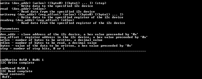
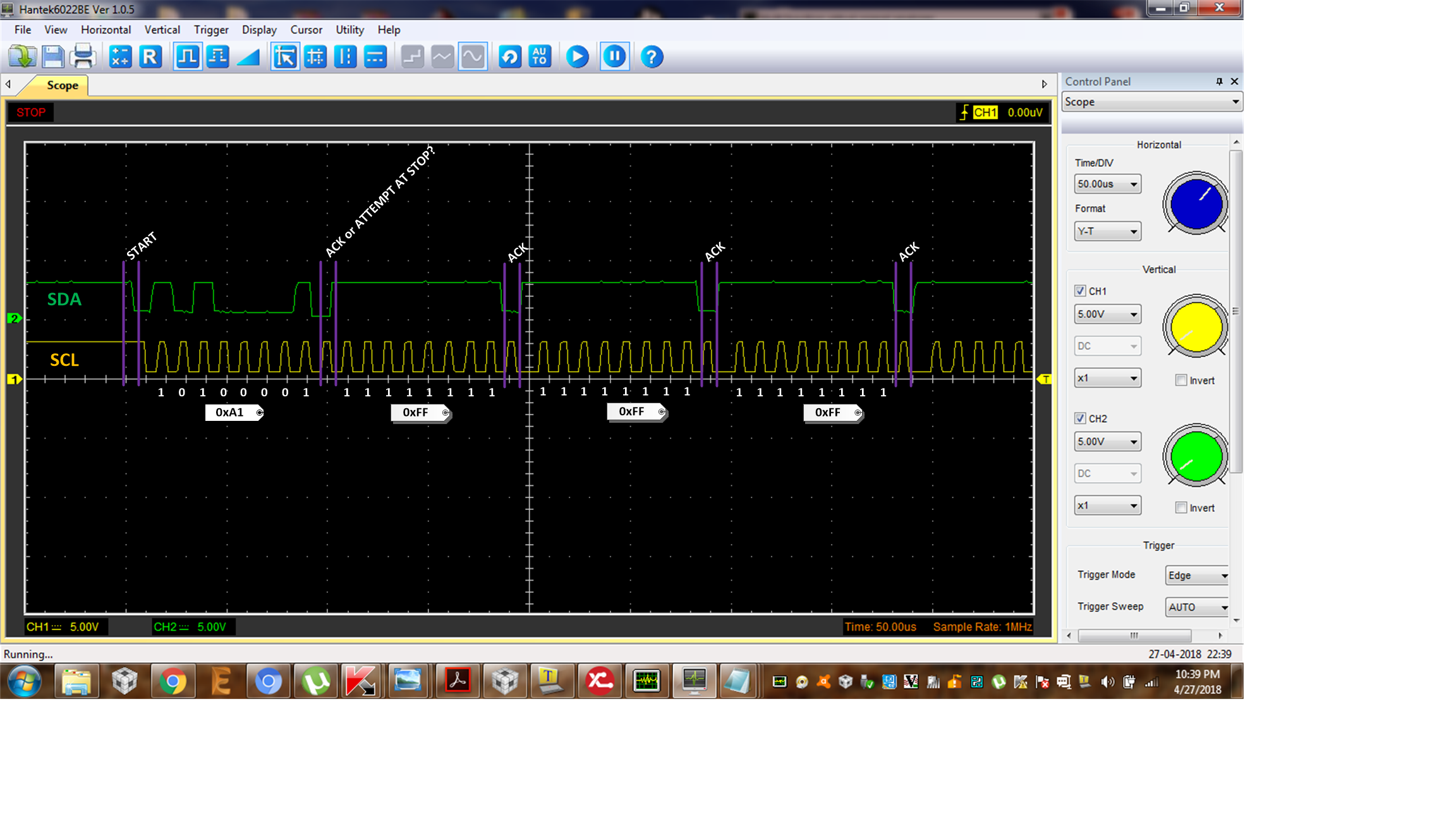
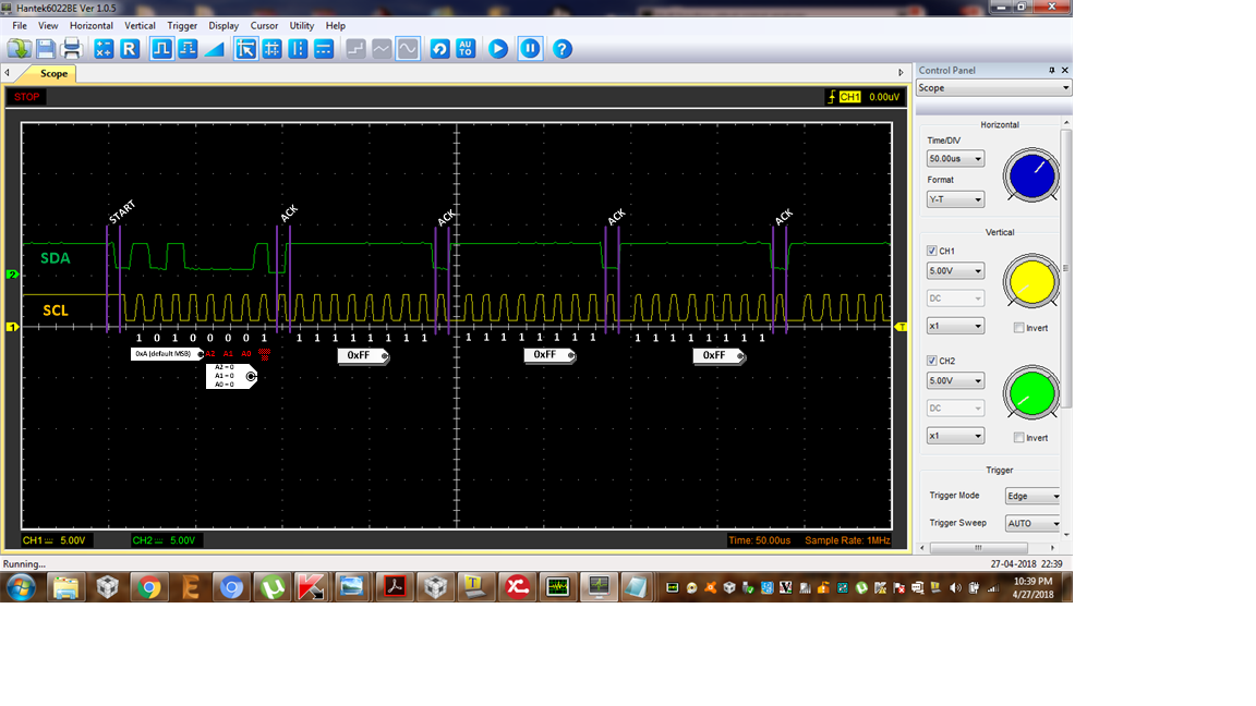
1, If i am writing  in EEPROM by either write cmd or write reg cmd in tera term   result is  I2C write complete. 

2. Now after writing if i am reading by either read or read reg command in tera team  always i get 0XFF.

3. If i read full 255 location of EEPROM  result are 0Xff always.

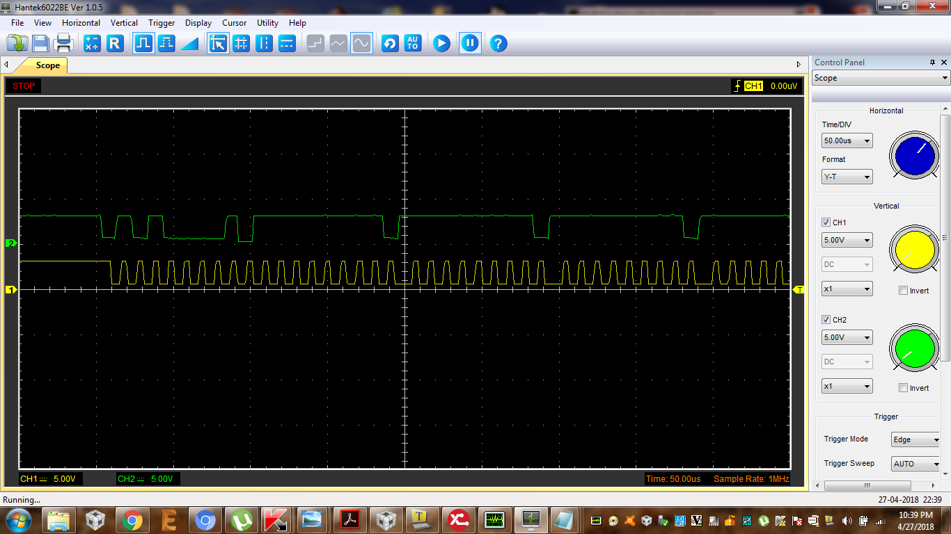
4. It seems that i am not able to write anything in EEPROM. So i tried to 7 bit addressing by replacing device id 0x50 to 0x51 for write operation but its result says ERROR IN PROCESSING CMD.  WP pin of EEPROM is grounded .

5. I am using 3.3volt pullup for SDA and SCL line . I got from data sheet for FST mode 400kbps speed  VCC should be 5 volt hence i have replaced fast mode to std mode in the code.

I struggled alot can anybody  tell me what is the problem in writing I2C EEPROM ??

screen shot are 


  • Abhay -
    From the datasheet of that I2C EEPROM (page 4), it states the Write Protect pin should be grounded for open access to read/write. Double check your soldering and schematic to match what the device requires. Then you should make sure to reference page 10 to address the part variant and the mode you want correctly. Then check with a logic analyzer that you are getting an ACK back every ninth byte.
  • Write protect bit is perfectly grounded. I will recheck with logic analyzer after that i will inform you. 

  • hello josh,

    My logic analyser is not working , i need to order new one.
    But i have gone through the complete i2c api in I2c demo code it is clear that we have to give device address . Write and read it will be take care by the APi itself .


    Below are my observation

    1. Device address 0x50 for at24c512 is absolutely right.
    2. We need not add write or read bit because api is 7 bit addressing and last bit will be added in the code by itself
    as below
    int
    I2C_IF_Write(unsigned char ucDevAddr,
    unsigned char *pucData,
    unsigned char ucLen,
    unsigned char ucStop)
    {
    RETERR_IF_TRUE(pucData == NULL);
    RETERR_IF_TRUE(ucLen == 0);
    //
    // Set I2C codec slave address
    //
    MAP_I2CMasterSlaveAddrSet(I2C_BASE, ucDevAddr, false);


    here in last line false is for write bit.


    3. I am getting error I2c read failed if i change dev addres to any of below

    0xA0
    0xA1

    but i never get error in case of read or write when dev address is 0x50.


    4. A0 and A1 pin of EEPROM are hardwired to GND.

    5. Schematic and soldering is perfact. If it would have been not than i should not get write complete and read complete
    result.


    6. I tried by keeping delay in write or read byte before next but it doesnot helped me.


    Please help me .

  • Still my issue is not resolved.
  • My issue is not resolved .
  • i think you should get logic analyzer or oscilloscope to troubleshoot this correctly
  •  hello josh,

    Thanks for your reply.

    here i am attaching the read data sequence .

  • It seems the everything is fine while reading and factory data may be 0xff at all location.

    I have checked writing cmd with i2c demo and what i got is always SDA and SCL lines are high. I think problem is in writing .

    Please suggest what should i do now.
  • Abhay -

    from the EEPROM datasheet ==>

    The AT24C04 uses the A2 and A1 inputs for hard wire addressing and a total of four 4K devices may be addressed on a single bus system. The A0 pin is a no connect and can be connected to ground. (you said you were doing this, but you also said you were connecting A1 to GND, too)

    AT24C04, 4K SERIAL EEPROM: Internally organized with 32 pages of 16 bytes each, the 4K requires a 9-bit data word address for random word addressing. (so you need to use 9 bit addressing - you said you were using 7 bit)

    so i modified your screen capture to show you were i think you are - in this case, i would either double check the schematic for the part you are using and also double check the code you have, in case you have modified or written your own. To me, if the address is supposed to be 0x50, this is not what you are sending - at least from what i can see that you sent over - i was referencing the data sheet of the EEPROM you are using, thinking that you are using the 4k part, since you referenced 512, which is how they call it out. 

  • Hello Josh,

    I am using AT24C512 . It is 512k  serial EEPROM.

    Here Address  0xA1 is correct address . Below is the bit sequence for addressing EEPROM

      1  0  1  0    0  A1  A0   R/W

    For reading EEPROM  and with A1 and A0 hardwired to GND  address will be  

     1 0  1 0   0 0    0  1    = 0xA1

    Above attached screen shot is for read hence 0xA1 is correct.

    Now the reason why i have used 0x50 address cmd in i2c demo  because the 8th bit will be taken care by below function

    int
    I2C_IF_Read(unsigned char ucDevAddr,
    unsigned char *pucData,
    unsigned char ucLen)
    {
    unsigned long ulCmdID;

    RETERR_IF_TRUE(pucData == NULL);
    RETERR_IF_TRUE(ucLen == 0);
    //
    // Set I2C codec slave address
    //
    MAP_I2CMasterSlaveAddrSet(I2C_BASE, ucDevAddr, true);
    //
    // Check if its a single receive or burst receive
    //
    if(ucLen == 1)
    {
    //
    // Configure for a single receive
    //
    ulCmdID = I2C_MASTER_CMD_SINGLE_RECEIVE;
    }
    else
    {
    //
    // Initiate a burst receive sequence
    //
    ulCmdID = I2C_MASTER_CMD_BURST_RECEIVE_START;
    }
    //
    // Initiate the transfer.
    //
    RET_IF_ERR(I2CTransact(ulCmdID));
    //
    // Decrement the count and increment the data pointer
    // to facilitate the next transfer
    //
    ucLen--;
    //
    // Loop until the completion of reception or error
    //
    while(ucLen)
    {
    //
    // Receive the byte over I2C
    //
    *pucData = MAP_I2CMasterDataGet(I2C_BASE);
    //
    // Decrement the count and increment the data pointer
    // to facilitate the next transfer
    //
    ucLen--;
    pucData++;
    if(ucLen)
    {
    //
    // Continue the reception
    //
    RET_IF_ERR(I2CTransact(I2C_MASTER_CMD_BURST_RECEIVE_CONT));
    }
    else
    {
    //
    // Complete the last reception
    //
    RET_IF_ERR(I2CTransact(I2C_MASTER_CMD_BURST_RECEIVE_FINISH));
    }
    }
    //
    // Receive the byte over I2C
    //
    *pucData = MAP_I2CMasterDataGet(I2C_BASE);

    return SUCCESS;
    }

     I have not changed anything in the code . I am using I2C demo example which is in CC3200 SDk.

  • Abhay -

    so this is actually the datasheet for the part you are using?

    thanks for pointing there - that allowed me to look at this a bit more, as this is a little better of a datasheet - and it matches the part - so based on section 9 - i am trying to figure out your intent.

    here is the modified annotation to your screen capture:

    this i think is now correctly labeled - and it does not match any of the Read Operations shown - the way i see it, if you were doing current address read, the part would have generated a stop condition after one byte (figure 9-1) on page 11 and if you were intending to do random read you would have sent first and second word addresses after device address, etc. (see Figure 9-2, also on page 11) and then there is sequential read, which is preceded by either the current address read or the random address read. 

    Double check your addressing please, as i see it you are sending 000 now and this would be allowed by the device if you leave all the lines floating (this what i see in the data sheet) - or you can set it to 0-7 (for eight possibles)

    A2, A1, A0  = 1b...device address is 7d

    A2=1b, A1=1b, A0=0b...device address is 6d

    A2=1b, A1=0b, A0=1b...device address is 5d

    A2=1b, A1=0b, A0=0b...device address is 4d

    A2=0b, A1=1b, A0=1b...device address is 3d

    A2=0b, A1=1b, A0=0b...device address is 2d

    A2=0b, A1=0b, A0=1b...device address is 1d

    A2=0b, A1=0b, A0=0b...device address is 0d

  • HELLO  JOSH,

    Thanks for your support , but i am still in trouble .

    Yes datasheet is exact.

    Yes 0d is correct and same i am using .

    I checked connection to A2,A1,A0 and they all are shorted and Grounded perfectly.

    If i am getting a Zero  (ACK )after sending first 8 bits of address from EEPROM that mean address for write is correct. Otherwise we will never get acknowledge bit from EEPROM(Last line of section 7 of EEPROM  data sheet)

    I have send the logic screen when when i was reading continuously   till 255 location hence the stop condition will come after complete reading of 255 location.

    As per I2c standard every STOP condition  shall be followed by START conditions and than address. You can see in section  9.2 and 9.3 stop condition always followed by start condition. but as i am reading continuously there should not be stop till end of read  .

     I will send below data sequence logic analyse screen shots by end of the day :

    1. One  byte current address read   i.e.  section  9.1

    3. Random read     i.e.  section   9.2

    4. Sequential read   i.e.  section  9.3

    5.  write  section 8

    Below is my understanding of    in red color comment   I2C_IF_Read  API  :

    int

    I2C_IF_Read(unsigned char ucDevAddr,

           unsigned char *pucData,

           unsigned char ucLen)

    {

       unsigned long ulCmdID;

       RETERR_IF_TRUE(pucData == NULL);     // If data which is to written is NUll than return  from this function with failure.

       RETERR_IF_TRUE(ucLen == 0);               // if data length is zero than reutrn from this function with failure.

       //

       // Set I2C codec slave address

       //

       MAP_I2CMasterSlaveAddrSet(I2C_BASE, ucDevAddr, true);         // This will set the Slave device id for Read operation  Here last bit will be added .   0x50  and true will give 0xA1 .                   

       //

       // Check if its a single receive or burst receive

       //

       if(ucLen == 1)    

       {

           //

           // Configure for a single receive

           //

           ulCmdID = I2C_MASTER_CMD_SINGLE_RECEIVE;

       }

       else

       {

           //

           // Initiate a burst receive sequence

           //

           ulCmdID = I2C_MASTER_CMD_BURST_RECEIVE_START;

       }

       //

       // Initiate the transfer.

       //

       RET_IF_ERR(I2CTransact(ulCmdID));

       //

       // Decrement the count and increment the data pointer

       // to facilitate the next transfer

       //

       ucLen--;

       //

       // Loop until the completion of reception or error

       //

       while(ucLen)

       {

           //

           // Receive the byte over I2C

           //

           *pucData = MAP_I2CMasterDataGet(I2C_BASE);

           //

           // Decrement the count and increment the data pointer

           // to facilitate the next transfer

           //

           ucLen--;

           pucData++;

           if(ucLen)

           {

               //

               // Continue the reception

               //                                                                      ///  SHALL I KEEP STOP CONDITION HERE ? Probably not .

               RET_IF_ERR(I2CTransact(I2C_MASTER_CMD_BURST_RECEIVE_CONT));

           }

           else

           {

               //

               // Complete the last reception

               //

               RET_IF_ERR(I2CTransact(I2C_MASTER_CMD_BURST_RECEIVE_FINISH));

           }

       }

       //

       // Receive the byte over I2C

       //

       *pucData = MAP_I2CMasterDataGet(I2C_BASE);

       return SUCCESS;

    }

  • Hi,

    I am confused from this thread. How looks all EEPROM write command? Do you properly write first and 2nd word of EEPROM address?

    Actually I use more EEPROM types (24LC02b, M24M01, M24M02) with CC3220 and CC3200 as well without any issue.

    Jan