This thread has been locked.

If you have a related question, please click the "Ask a related question" button in the top right corner. The newly created question will be automatically linked to this question.

CCS/CC3200: Launchpad cannot debug

Part Number: CC3200
Other Parts Discussed in Thread: UNIFLASH,

Tool/software: Code Composer Studio

Hi,

Iam using CC3200 Launchpad and learning TI CC3200 for my new project. it was works fine last 2 week and suddenly stop. I cannot debug from CCS , but can able to flash by Uniflash. I don'r know what was changed in my PC or CCS. I can able to flash and not debug.

Cortex_M4_0: Can't Run Target CPU
Cortex_M4_0: Error
Cortex_M4_0: Unable to determine target status after 20 attempts


This is the error message on my console window. One more thing , if i connect J16( flash programming ) CCS can flash but still not able to debug and have above error.

Please anyone know the solution / this scenario please help me to come out from this...  

  • Hi,

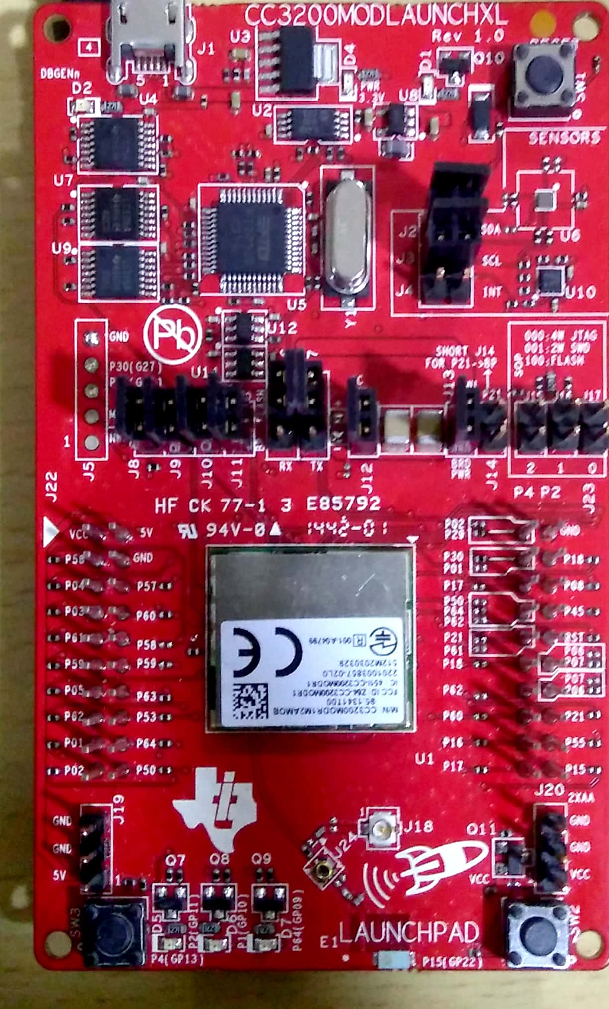
    Please provide photo how do you have connected jumpers.

    Jan
  • Yes. sure. I did not change any jumper. For flash programming ( uniflash ) i did change.... But for debuging from ccs no connection on SOP

  • Hi,

    OK, your jumpers configuration looks OK.

    - Do you see in device manager COM port "CC3220LP Dual Port"?
    - Please make sure that you have selected in CCS target configuration file for CC3200 and selected JTAG (not SWD).
    - What connection "debugger" do you have selected in target configuration?

    Jan
  • Target configuration i just follow "project 0" in youtube one.... I not remember, i did  change on here...

  • Hi,

    It looks OK.

    - Do you see "CC3220LP Dual Port" in device manager?
    - Make sure that you not have connected terminal software to COM port.
    - Do you have another debug probe (XDS100, XDS110) or LaunchPad? Maybe you could try connect external debugger.

    Jan

  • Sorry i don't have external debugger. serial port terminal ( Teraterm ) can connect to launchpad and can communicate.

    One more observation I was connected SOP in 100 ( flash) mode and run example project can able to debug. So some settinging i hope changed in my project ? 

  • Hi,

    Just to be sure... You are able connect/debug some other example project now? Only your project is not functional, right?

    Jan
  • yes. you are right. the SDK example project can run in RAM.... but what i can do for debug/programming in project setting ?

    but cannot saw it "example"  is running in RAM... because i was connected SOP Jumper on 100. 

  • Hi,

    In case that you are able debug examples form SDK, we are sure that hardware is OK.

    What can be wrong at your project:
    - you have not selected target configuration for your CC3200 project, check if CC3200.ccxml is set as default
    - check your pinmux settings GPIO pins GPIO23, GPIO24. This pins are shared with JTAG lines (TDI, TDO). In case that you select this pins as GPIO, debug via 4 wire JTAG is not possible

    Jan
  • Yes. This I already checked in pinmux generated file. I don't see any conflict and below is that. the Modular 22 pin (PIN_15) was used as gpio is it sharing debug / programming ?.  


    //
    // Configure PIN_64 for GPIO Output
    //
    PinTypeGPIO(PIN_64, PIN_MODE_0, false);
    GPIODirModeSet(GPIOA1_BASE, 0x2, GPIO_DIR_MODE_OUT);

    //
    // Configure PIN_01 for GPIO Output
    //
    PinTypeGPIO(PIN_01, PIN_MODE_0, false);
    GPIODirModeSet(GPIOA1_BASE, 0x4, GPIO_DIR_MODE_OUT);

    //
    // Configure PIN_02 for GPIO Output
    //
    PinTypeGPIO(PIN_02, PIN_MODE_0, false);
    GPIODirModeSet(GPIOA1_BASE, 0x8, GPIO_DIR_MODE_OUT);

    //
    // Configure PIN_04 for GPIO Input
    //
    PinTypeGPIO(PIN_04, PIN_MODE_0, false);
    GPIODirModeSet(GPIOA1_BASE, 0x20, GPIO_DIR_MODE_IN);

    //
    // Configure PIN_15 for GPIO Input
    //
    PinTypeGPIO(PIN_15, PIN_MODE_0, false);
    GPIODirModeSet(GPIOA2_BASE, 0x40, GPIO_DIR_MODE_IN);

    //
    // Configure PIN_55 for UART0 UART0_TX
    //
    PinTypeUART(PIN_55, PIN_MODE_3);

    //
    // Configure PIN_57 for UART0 UART0_RX
    //
    PinTypeUART(PIN_57, PIN_MODE_3);

    //
    // Configure PIN_58 for UART1 UART1_TX
    //
    PinTypeUART(PIN_16, PIN_MODE_2);

    //
    // Configure PIN_45 for UART1 UART1_RX
    //
    PinTypeUART(PIN_45, PIN_MODE_2);
    }

  • Hi,

    Hmm... I haven't idea what else can be wrong than not properly set target configuration.

    Maybe better way than elaborating what can be wrong will be get it to work. I think you should try import new project from SDK, remove all *.c and *.h from it and copy there your source *.c and *.h.

    Jan
  • Dear fastmahesh -
    Did you try installing J15 ?
  • Yes. That is the jamper SOP ( 100). without that my board and pc not communicating...

    My PC side I was checked any change, yes there is a windows update. but will it effect CCS debug ?

    I was tried to flash FDI chip also... 

  • Dear fastmahesh -
    you need the SOP jumper on there. makes complete sense you cannot communicate without it.
    you should not have had to flash a template onto the FTDI IC.
  • is there anyway to reset lauchpad board.....
    problem is it is not running from RAM... so any configuration on debug module changed ?
  • yes. without J15 cannot connect board.
  • there is a reset button on the top right corner of the board.
    i am not sure exactly what you are asking on the second question.
    we have not changed anything on the FTDI side in (at least) two years.