This thread has been locked.

If you have a related question, please click the "Ask a related question" button in the top right corner. The newly created question will be automatically linked to this question.

Unable to flash the CC3220MODASF launchpad

Part Number: LAUNCHCC3220MODASF
Other Parts Discussed in Thread: UNIFLASH, CC3220SF, ENERGYTRACE, TPS62162

Tool/software: Code Composer Studio

Hi,

I am trying to flash a CC3220MODASF launchpad using the Uniflash Tool in development mode.

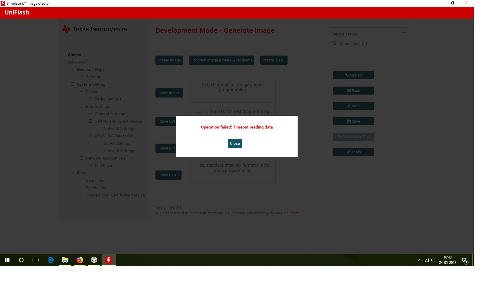
But when I click on connect to connect my launchpad kit for flashing It shows an error : Operation failed: Timeout reading data.

Then I tried to debug the code using Code Composer Studio. It is showing an error: An internal error occurred during: "Launching gpiointerrupt_CC3220SF_LAUNCHXL_nortos_ccs".
com/ti/dvt/energytrace/af/PowerActivity

Also I tried to factory reset the launchpad, but it doesn't work.

Please suggest me how I can resolve this problem.

  • Sagar,

    Can you share a picture of your board so i can check jumper configurations? Also keep the board powered so I can check LEDs.

    Thanks,

    VR
  • Hi Vincent,

    I have sent the picture of launchpad, also now I have reinstall the the code composer studio this resolves my energy trace issue as shown in post : https://e2e.ti.com/support/development_tools/code_composer_studio/f/81/t/534520?Unfamiliar-CCS-error-message

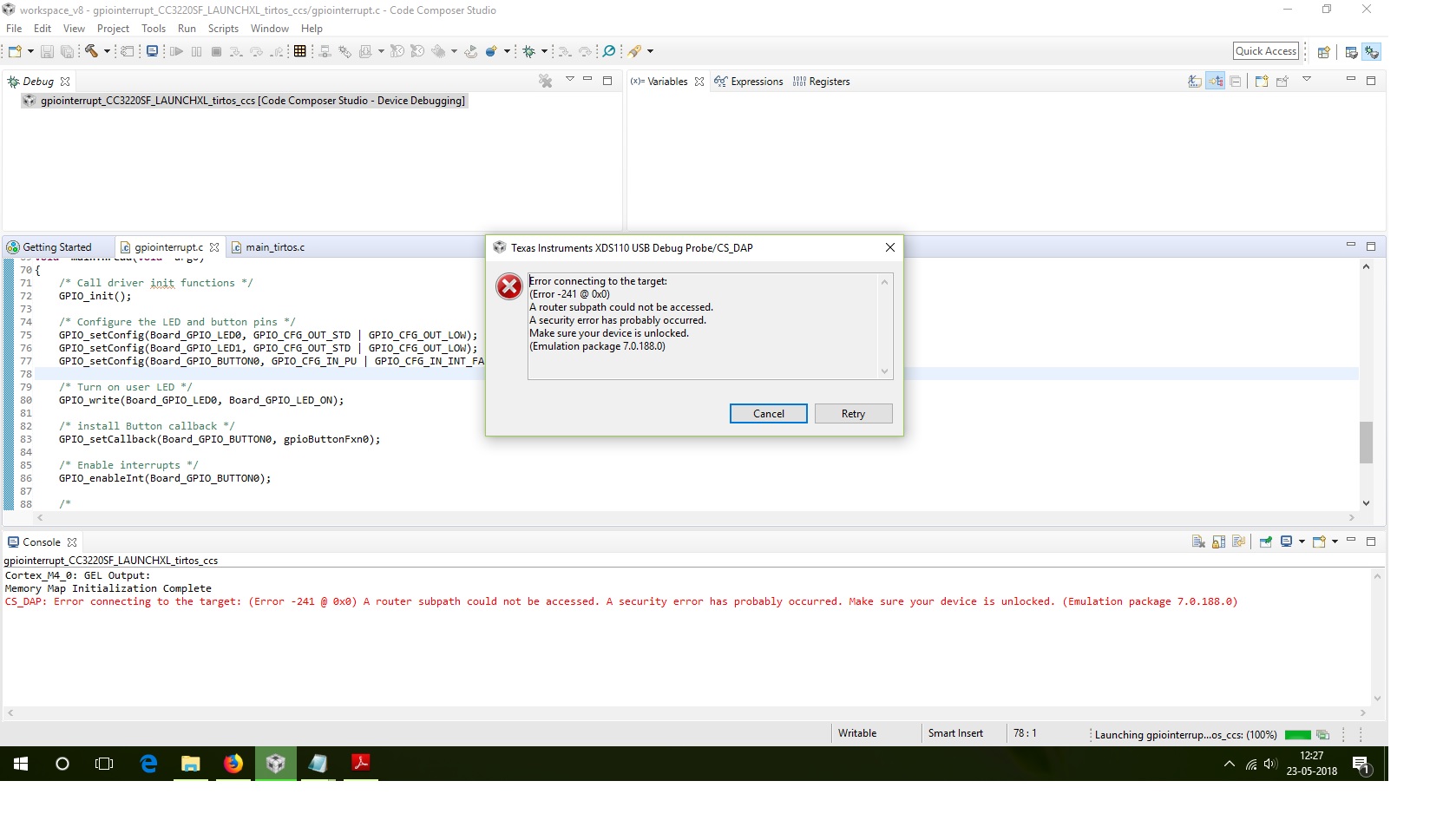
    But now when I debug the program it is showing me the error: Error connecting to the target:

    (Error -241 @ 0x0)

  • That error is typical if the device has been flashed in production mode. In this mode the device cannot be debugged. Can you reflash the device in development mode and see if the error still occurs?

    Regards,

    VR
  • I have tried to connect the launchpad to Uniflash Tool in development mode but it is giving me an error: Operation failed: Timeout reading data and

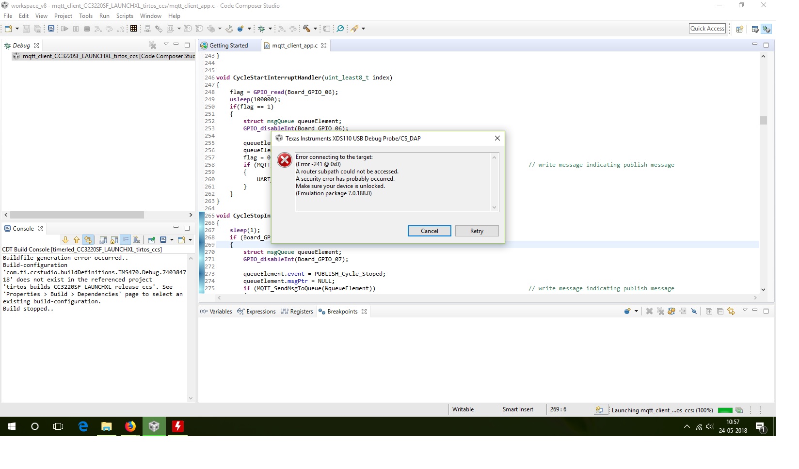
    when I debug the program it gives me an error :

    Error connecting to the target:
    (Error -241 @ 0x0)
    A router subpath could not be accessed.
    A security error has probably occurred.
    Make sure your device is unlocked.
    (Emulation package 7.0.188.0)

    Also I have another cc3200sf launchpad when I connect this to Uniflash tool it works fine.

  • Hmm, Looks like you are unable to communicate to the device.

    Can you ensure the jumpers are configured the same as Figure. 1-4 of the users guide?

    www.ti.com/.../swru512.pdf


    VR
  • Hi Vincent,

    Sorry for late reply, I have checked the jumper settings. They all are as per fig.

  • Hi Vincent,

    Sorry for late reply

    I have checked the jumpers all are as per fig.

    Is there any other way to reset the device or for troubleshooting, please suggest me it will be great help.

  • Sagar,

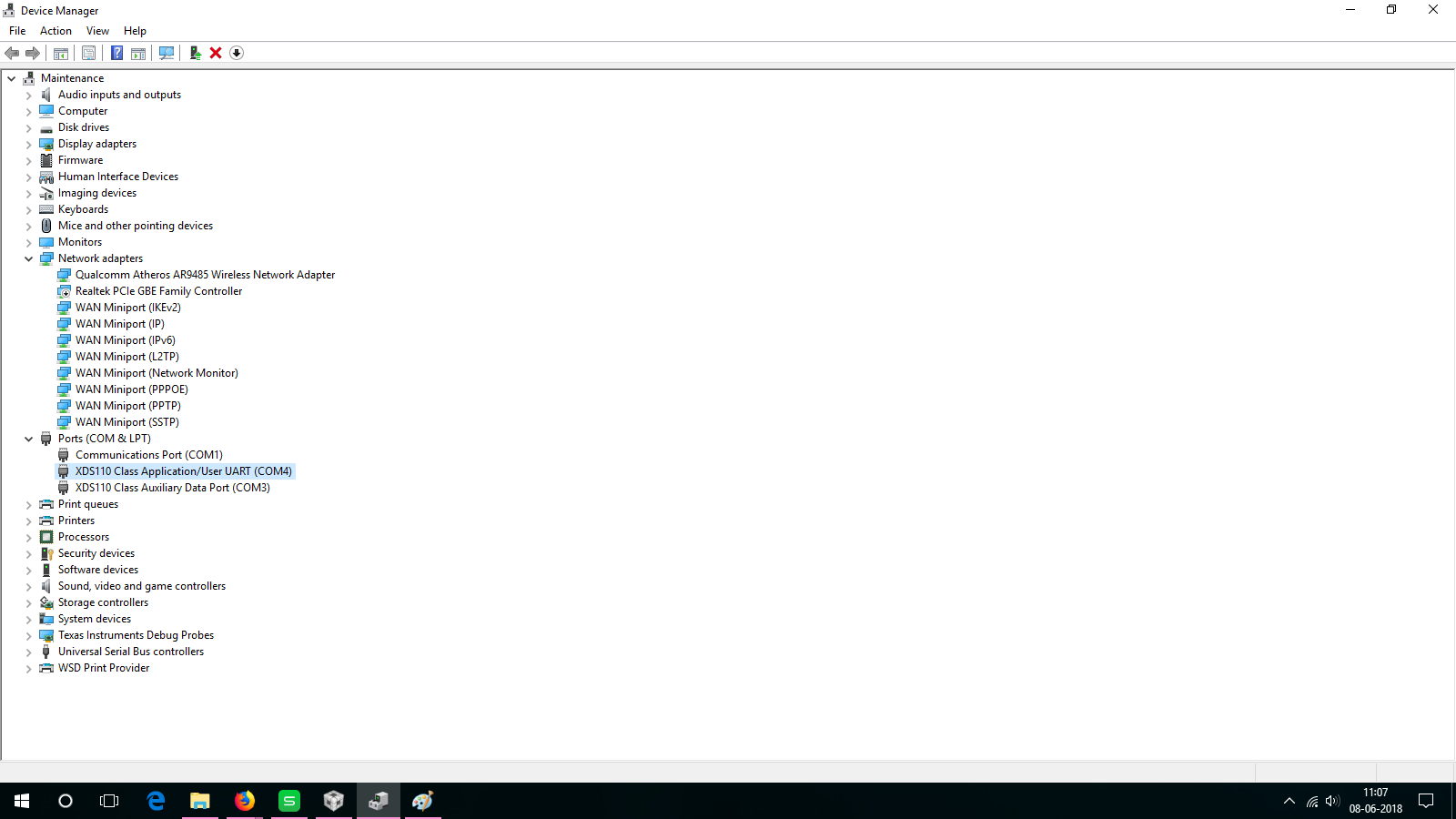
    Can you check and make sure you see the device in your Device Manager? Also make sure another program isn't using the COM port (TeraTerm or Putty).

    VR
  • Hi Vincent,

    I have checked the ports in device manager, also there is no other device is connected so port is not used by other device.

    I have attached the screenshot of device manager

    But it is not connecting through the uniflash. Same timeout error is pop-up.

  • Sagar,

    Just to reclarify, you have two CC3220SF launchpads, and only one of them can be debugged or programmed correct? The one that doesn't work shows in your Device manager, but image creator and ccs is unable to flash/debug it.

    Have you been able to flash/debug the board before?

    VR
  • Hi Vincent,

    Yes, board is working properly earlier, I have flash it before. But now when I connect it in uniflash to flash a program it is giving me a timeout error.

    Also with same configuration I am able to flash the other board.

  • Sagar,

    Are you still having issues here?

    VR
  • Hi Vincent,

    Thanks for asking, I have tried all the possibilities of troubleshooting but it does not resolve my issue.

    Can you please suggest me what should I do now ?

  • Hi Vincent,
    I was unable to use the other board now it is showing me same error.
    It worked well up to yesterday but now it is showing me same error as the first board.
    Also at 3.3V header it is showing me an 3.99 V at the J21 header and 5.11V at J22 header which should be 3.3V and 5V
    Please help me out to solve this issue because now I am unable to debug or flash either board.
    Due to this I am unable to proceed in my project.
  • Hi,

    Please remove jumper VBAT jumper (J18) and measure voltage. In case of that you have oscilloscope available, please measure ripple at J18.

    5.11V at J22 not look a problem but 3.99V at J21 looks as problem with Step-Down Converter (TPS62162) at LP. How do you use board? What external circuits do you connect to LP? How do you power LP?

    Jan

  • Hi Jan,

    I am having USB connection issue with both the launchpads
    After removing the VBAT jumper I get 2.626 V at the 3.3V header. To power up this board I have use the 5V SMPS across J22 - 5V jumper.


    But on the other board I am getting 3.3V with VBAT jumper and 0V when VBAT jumper is removed.

    Also I am unable to debug or flash either of the boards.
    I am getting error : Error connecting to the target: (Error -1170 @ 0x0) Unable to access the DAP, whenever I tried to debug it.

    Can I bring it to nearby Texas center located (at Pune) as I am unable to figure out reason behind this connection issue.

    Please help me out to resolve this issue.

  • Hi,

    Please measure voltage at top PIN (near to XDS-110) in case of disconnected jumper J18.

    You want to say that you have connected external 5V via J22, connected LP to computer via USB and had closed jumper J19 (5V) at same moment? In this moment you have connected external 5V from J22 to your USB port at computer. And this is really not a good idea.

    Jan

  • Hi Jan,

    I am using CC3220MODASF launchpad, It has J21 for 3.3V and J22 for 5V.

    I have connected the external supply to J22, after flashing the launchpad and removed the USB cable so it is disconnected from the computer.

  • Hi,

    OK, can you share voltage on J18 (pin next to XDS-110)?

    Jan
  • Hi Jan and Vincent,

    for the launchpad I am using J18 is the VBAT jumper which is giving a voltage of 2.4V,

    Also I have  updated to firmware of the CC3220MODASF launchpad. After resetting the board and updating the firmware file one of the board is now connecting to the debug and also now I can flash it.

    Firmware is updated using "xdsdfu Tool" which is at location : ti\ccsv8\ccs_base\common\uscif\xds110

    But the launchpad which is working after resetting the firmware is giving a 3.9 V at the 3.3V connector, is it safe to use as it is or it ma damage other circuit on the board ?

    Also about the other board I am still unable to flash it. I couldn't get it if both launchpad shows same error but after resetting board and updating firmware why this launchpad is not working.

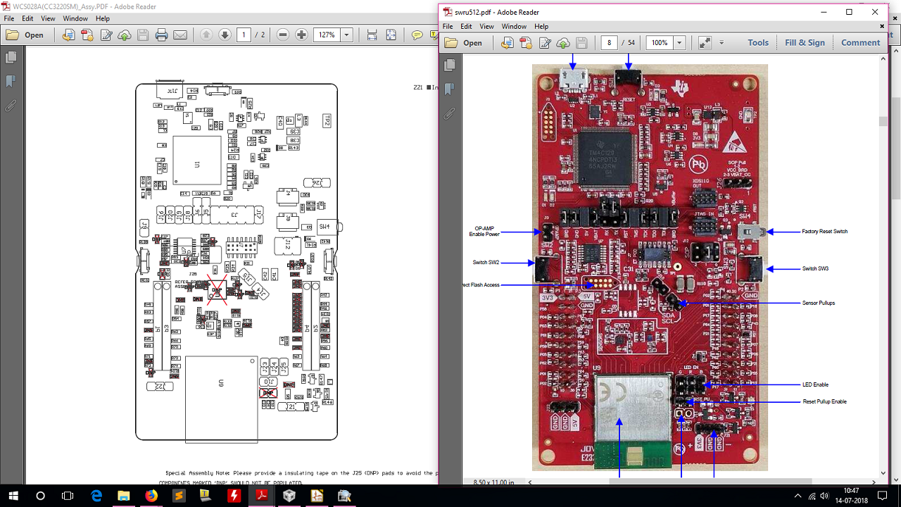
    Here is the assembly file and launchpad picture.

  • Hi,

    3.9V at 3.3V connector is bad really. Is more than allowed maximum for CC3220SF chip (3.8V) and pretty close to maximum of TM4129 chip used as XDS110 debugger (4.0V). I am not able say that chips are damaged already.

    Still did not give me requested voltage. I need to know output voltage from dc-dc (TPS62162) without connected CC3220. I will try better describe what I need. Follow steps:

    1. Disconnect jumpers J18, J16
    2. Disconnect all your boards from LP
    3. Connect LP only by USB
    4. Measure voltage at point described below:

    If I should speculate what you do wrong. I think you have something wrong at circuits that you connecting to LaunchPad. For example you are connecting 5V directly to inputs of CC3220, etc. Can you provide more information what external and how you connect to LP board?

    Jan

  • Hi Jan,
    I have measure the voltage as you told, I got 5.11V at J19 and 4.25V volt at J18.
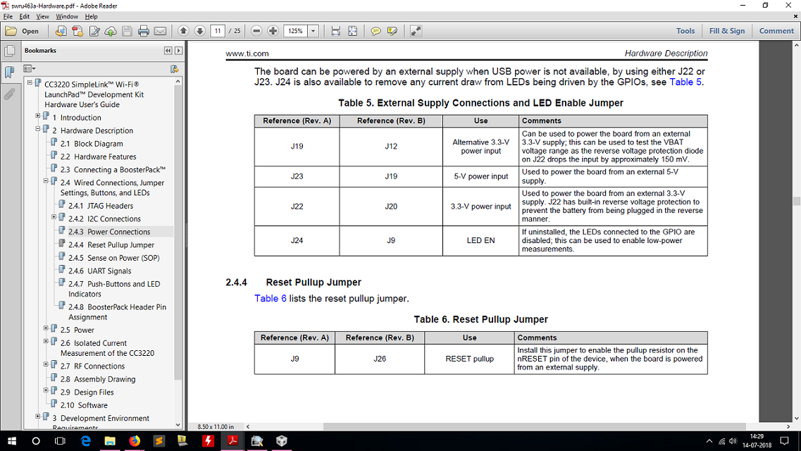
     and previously to power up this LP Board, after flashing the LP I have connected 5 V SMPS to J22 5V jumper and removed the USB cable as given in the hardware user guide of the SimplelinkCC3220. I have attach the screenshot.

    Now when I debug it with example which are using the peripherals like timerled or gpiointerrupt it works well but when I debug MQTT or Out of Box example it gives an error :

    Cortex_M4_0: GEL Output:
    Memory Map Initialization Complete
    Cortex_M4_0: GEL Output:
    Target Reset
    Cortex_M4_0: JTAG Communication Error: (Error -261 @ 0x0) Invalid response was received from the XDS110. (Emulation package 8.0.27.9)
    Cortex_M4_0: Failed to remove the debug state from the target before disconnecting.  There may still be breakpoint op-codes embedded in program memory.  It is recommended that you reset the emulator before you connect and reload your program before you continue debugging

    after placing the breakpoints in the program I observed that at function sl_Start it is giving an JTAG communication error

    on line    -       retc = sl_Start(0, 0, 0); 

  • Hi,

    That is even worse. It looks that you have somehow damaged dc-dc converter TPS62162 or chips connected to VCC_LDO_3V3 (probably only TM4C129) rail or VCC_LDO_3V3 rail connected to 5V.
    - Are you able look to voltage at J18 by the oscilloscope?
    - Are you able check if TPS62162 chip is not hot?
    - Are you able measure current flowing via jumper J19 and overall current via USB?
    - Please check if is not connected +5V rail to +3.3V rail by jumpers.

    I think it is likely that chips at board are already damaged. Maybe short time connection to Vcc=4.25 can chips (CC3220, TM4C129) can survive, but for a long time probably not.

    Update: in case of call sl_Start(0, 0, 0); is enabled NWP and it requires much higher current. Probably power source (TPS62162) is not able provide this current. All indications shows that TPS62162 is toasted already. Maybe other chips ware still surviving, but in cannot survive 4.25V for a longer time.

    Jan

  • Hi Hnz,
    At J18(VBAT) I get 3.9V and 33.2mA, also TPS62162 IC is not hot and the current flowing through the J19(5V) jumper is 0A.

    But on the second board I am getting 3.3V at the VBAT jumper and J21 jumper. The only problem is
    I am getting error : Error connecting to the target: (Error -1170 @ 0x0) Unable to access the DAP, everytimeI tried to debug it
    and timeout error during flashing the program on it.
    Can you please suggest me, How could I resolve this problem.

    Because I am unable to proceed in project as both LP boards are not functioning now.
  • Hi,

    First board with 3.9V at J18 have damaged TPS62162 dc-dc probably and maybe other chips too. Another option can be that VCC_LDO_3V3 is connected to +5V somehow (via some damaged chip, via relative low resistance, etc.). Maybe it could be possible use with this board external 3.3V power supply source, but who knows.

    Meaning of error at 2nd board is that XDS is not possible connect to JTAG. Likely this error is shown when board is not set into development mode by the Uniflash software. But I am not sure, if this error cannot be shown in case of damaged CC3220 chip. You should try to use Uniflash and set into development mode.

    I am not a TI employee. From this reasons I am not able help you with yours damaged LaunchPads. If you share more information what and how do you connect to LaunchPad I looks to potential reasons what is killing your LaunchPads. I think your mains goal should be determine why your other circuits killing LaunchPads.

    Jan
  • Hi Hnz,

    As I described before I have connected the 5V SMPS to J22 (5V jumper of LP) to power the LP and

    after that  voltage regulator IC TPC62162 is damaged and due to this voltage I get at 3.3V jumper is 3.9V.

    Also I am flashing the other LP in development mode but still it is giving a same debug error.

    Can you tell me how could I change the firmware and boot loader files of the TM4C emulator IC.

  • Hi,

    Sorry, I am not sure how I could help you. As first thing you should determine reasons what killed your LP or both. For this purpose you will take voltmeter and oscilloscope and according schematic try figure out what is going on. Questions related to TPS62162 you can ask at e2e.ti.com/.../196

    Questions related to XDS debugger, please ask at CCS forum ( e2e.ti.com/.../81 ).

    Jan