This thread has been locked.

If you have a related question, please click the "Ask a related question" button in the top right corner. The newly created question will be automatically linked to this question.

(Error -1170 @ 0x0) Unable to access the DAP.

Part Number: CC3220SF
Other Parts Discussed in Thread: UNIFLASH, , CC3220MOD, CC3200MOD

Tool/software: Code Composer Studio

Hello,

I have tried the solution proposed in the linked thread but that didn't work for me: at the step where you connect directly to the DAP (right click on it and then "connect target") i still get the same error (Unable to access the DAP etc). 

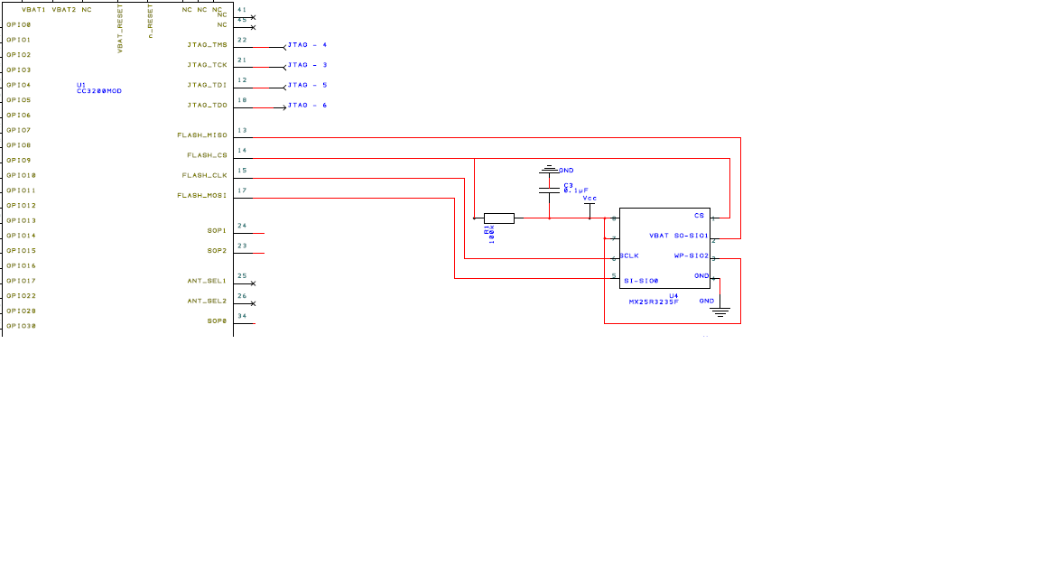
I also have made a custom board but with the CC3220SF. I have the 4 JTAG signals accessible (TDO, TDI, TCK and TMS). I connect the XDS110 probe to my board with the 20 to 14pins adaptator. 

The SOP jumpers are set to pull-down (FUNCTIONAL_4WJ) and the board is externally powered (3.3V). 

Which tests can i run to see what's happening? I double checked the hardware and everything seems fine. 

Any help would be greatly appreciated!

Thanks in advance!

Kateline 

  • Hi,

    Do you have switched your CC3220 into development mode by Uniflash software? This procedure is mandatory to be debug via JTAG/SWD enabled.

    Jan
  • Hi Jan, thanks for your answer!
    I didn't do that... But it doesn't work: uniflash doesn't detect the chip.
    I have, on the board, a USB connector that goes through a FT230X to create the RX/TX/CTS/RTS_USB signals for the CC3220SF.
    My computer detects that there is a new device connected: it sees a new USB Serial Port (COM PORT) but uniflash doesn't find the CC3220SF (manual or auto detection mode).
    Thanks again for your help,
    Kateline
  • Hi Kateline,

    Connection from Uniflash GUI works only with UART from XDS-110 debugger. With general COM port (as yours from FT230X) you may to use Uniflash CLI. In case of that you have XDS-110, easiest way is to use UART from XDS-110.

    Jan
  • Hi Jan,
    Thanks for your fast answer! I'll try that, and let you know!
    Thanks again!
    Kateline
  • Hello,

    So I tried to connect via the UART but still doesn't work.

    Uniflash sees the XDS 110 but doesn't detect the type of chip:

     And when i click to select the device manually, the CC3220SF is not in the list (in fact it doesn't find anything starting with "CC3"). 

    So I do the selection manually (bottom part of the pannel). But then, when i start a new project and try to connect to the device, i get the following message: 

    Is this a problem with the hardware on my board? For the UART I have RX and TX connected to GPIO4 and GPIO16 respectively. I have, for another application, CTS also connected to the chip, does that change something? Are the GPIO4 and GPIO16 by default in UART mode? 

    Maybe is the XDS110 not properly configured? 

    Thanks again for your help,

    Kateline 

  • Hi Kateline,

    Uniflash communicate with CC3220 in bootloader mode. In this mode need to be used RX, TX at pins with alias GPIO_01, GPIO_02 only. Other UART pins cannot be used.

    BTW ... what version of Uniflash do you use?

    Jan

  • Hi Jan,
    Things start to get clearer, thanks a lot for your answer, i'll see what i can do to access those...
    I'm working with the version 4.2.0.1490.
    Kateline
  • Hi,

    Version 4.2.0 should be OK. I use version 4.2.2.

    Jan
  • Ok!
    Just to be sure all i need from the XDS110 to the board are the following:
    UARTRX(xds110) --> GPIO1(TX cc3220),
    UARTTX(xds110) --> GPIO2 (RX CC3220),
    GND (xds110) --> GND board.
    No Vsense or other?
    Thanks again,
    Kateline
  • Hi Kateline,

    Unfortunately I haven't stand-alone XDS-110, from this reasons I not know proper answer.
    - RX, RX, GND ... that is OK
    - Vsense ... I am not sure, but probably is not mandatory
    - It could be necessary connect PA6 from XDS-110 to CC3220 reset ... I am not sure

    Jan
  • Hi Jan,
    Switching the GPIO ports helped me access the CC3220 via uniflash and set it in programmation mode so it solved my question! thanks a lot :)
    However i clicked the button a little to fast: in CCS i still get the "unable to access DAP" message... What else could i check?
    thanks again,
    Kateline
  • Hi Kateline,

    In case of you cc3220 is properly set into development mode (please check image in Uniflash):

    You should check this:

    - that JTAG pins are properly connected (TDO, TDI, TCK, TMS, GND)

    - you have set proper SOP configuration (JTAG/SWD) according set target configuration in CCS

    - make sure that you not have uploaded firmware image inside sFlash which switch JTAG pins to alternate function (=upload empty image by Uniflash)

    Jan

  • Hi Jan,

    I didn't notice but in regard of "Current Mode" I have "No file system" (see the image below). 

    Do i need to flash something to the chip? 

    - for the JTAG: i already checked the connexions and i'm pretty sure they are ok (i'll check again to be 100% sure). Question: it is each signal connected to the same from one side to the other? (TMS-TMS, TDI-TDI,...?) 

    - SOP is set 000 thus FUNCTIONNAL_4WJ = debug via JTAG 4 ways (correct?) 

    - i have never uploader any software on my custom board so i think i'm safe for this point.

    Thanks again (very very much) for your help, my projet is finally moving forward! 

    Kateline

  • Hi Kateline,

    Your CC3220 is not in development mode. Image with development mode was not uploaded into flash chip. See image below:

    Description how to use Uniflash with CC3220 you find here http://www.ti.com/lit/pdf/swru469

    Jan

  • Hello,

    So I tried to program the image on the chip (as you described above) but i get the same message i got in the beginning:

    After that, the device appears as disconnected in uniflash and i can't reconnect it directly: i have to reboot it (take the battery off then replug it). 

    I didn't change anything to the connexions in between... 

    Any idea?

    Kateline 

    EDIT: i've noticed just now that when i click on "program image", the window with "creating image" shows up, the device is still connected but then right after the window updates to "starting...", the device's status changes to disconnected! 

  • Hi Kateline,

    I haven't much ideas why it is not working writing image from Uniflash GUI. How do you have currently set SOP configuration? Do you have connected RST pin to CC3220 to XDS-110?

    If you have already created image by Uniflash GUI, you can try program image via Uniflash CLI. Command line command can look like:

    c:\ti\uniflash\dslite --mode cc3220 project program --name your_project_name --port COM5 --dev

    Jan
  • Jan,
    The RST pin of the CC3220 is not connected to the XDS. Where do I need to connect it? On the Aux breakout board?
    I'll check uniflash CLI,
    thanks again for all your help,
    Kateline
  • Hi Kateline,

    As first thing please try use Uniflash CLI, I think it will be functional even with your FTDI chip.

    I am not sure where connect RST pin to external XDS-110. At CC3220SF LaunchPad is integrated XDS-110 and RST pin or CC3220 is connected to pin PA6 (see design files for CC3220SF-LAUNCHXL).

    Jan
  • Hi Jan,
    I'll try uniflash CLI today, i'll let you know.
    At the end, i bypassed the FTDI chip to be more sure of the hardware: I've taken out GPIO1 and GPIO2 of the CC3220SF and connected directly to them.
    I've connected the n_RESET pin of the CC3220SF to the n_reset signal of the XDS110 (following what i've seen from the launchpad datasheet). I've monitored this pin with an oscilloscope and it seems to do its job: is goes to 0 at some point (uniflash indicates that the device is disconnected - logical) and then goes again up to 3V but uniflash doesn't "see" it - the device's status remains disconnected --> i don't know if that's normal (?).

    Regards,
    Kateline

    EDIT: see below the result of uniflash CLI --> i get the FS_ERR_FAILED_WRITE_NVMEM_HEADER error at the end. At the beginning it seems that a config file is missing: 'cfg.json'? 

    C:\ti\uniflash_4.1>dslite --mode cc3220 project program --name customBoard1 --port COM8 --dev
    Executing the following command:
    > C:\ti\uniflash_4.1\simplelink\gen2\bin\SLImageCreator.exe project program --name customBoard1 --port COM8 --dev

    Config file load error ([Errno 2] No such file or directory: 'cfg.json'), using defaults
    INFO:slbootloader.slbootloader:Connecting to device
    INFO:slbootloader.slbootloader:--- Please power off the device ---
    Press ENTER to continue
    INFO:slbootloader.slbootloader:Power off
    INFO:slbootloader.slbootloader:Set break signal
    INFO:slbootloader.slbootloader:--- Please power on the device ---
    INFO:slbootloader.slbootloader:Power on
    INFO:slbootloader.slbootloader:Clear break signal
    INFO:slbootloader.slbootloader:Connection succeeded
    INFO:slbootloader.slbootloader:Received storage list

    ------------------------

    Copyright 2014 TI.com. All rights reserved, SimpleLink programming image builder
    Builder = 3.0.1.3

    Interface version = 1.0.2.16
    Recommended command line window resolution W124 X H67

    The output directory is :[C:\Users\kdriessens\.SLImageCreator\projects\customBoard1\sl_image]
    The XML file is :[C:\Users\kdriessens\.SLImageCreator\projects\customBoard1\sl_image\ImageConfig.xml]

    Validate the XML against the schema.

    The XML validation passed.


    ------------------------

    Commands Set Number = 0
    CommandNum = 0
    CommandFormatStorage:
    CommandNum = 1
    CommandWriteCertificateStore:
    FileLocation = ../files\certstore.lst
    FileSystemName = /sys/certstore.lst
    File max size is 7000 bytes, actual size 3640 bytes
    After running the extracting the file will require 4 blocks on the device
    CommandNum = 2
    CommandWriteSystemFile:
    FileLocation = C:\Users\kdriessens\.SLImageCreator\projects\customBoard1\sl_fs\sys\ipcfg.bin
    FileSystemName = 17
    File max size is 200 bytes, actual size 200 bytes
    After running the extracting the file will require 2 blocks on the device
    CommandNum = 3
    CommandWriteSystemFile:
    FileLocation = C:\Users\kdriessens\.SLImageCreator\projects\customBoard1\sl_fs\sys\device.name.bin
    FileSystemName = 5
    File max size is 98 bytes, actual size 98 bytes
    After running the extracting the file will require 2 blocks on the device
    CommandNum = 4
    CommandWriteSystemFile:
    FileLocation = C:\Users\kdriessens\.SLImageCreator\projects\customBoard1\sl_fs\sys\ap.cfg.bin
    FileSystemName = 1
    File max size is 158 bytes, actual size 158 bytes
    After running the extracting the file will require 2 blocks on the device
    CommandNum = 5
    CommandWriteSystemFile:
    FileLocation = C:\Users\kdriessens\.SLImageCreator\projects\customBoard1\sl_fs\sys\mode.cfg.bin
    FileSystemName = 0
    File max size is 80 bytes, actual size 80 bytes
    After running the extracting the file will require 2 blocks on the device
    CommandNum = 6
    CommandWriteSystemFile:
    FileLocation = C:\Users\kdriessens\.SLImageCreator\projects\customBoard1\sl_fs\sys\sta.cfg.bin
    FileSystemName = 12
    File max size is 116 bytes, actual size 116 bytes
    After running the extracting the file will require 2 blocks on the device
    CommandNum = 7
    CommandWriteSystemFile:
    FileLocation = C:\Users\kdriessens\.SLImageCreator\projects\customBoard1\sl_fs\sys\dhcpsrv.cfg.bin
    FileSystemName = 3
    File max size is 12 bytes, actual size 12 bytes
    After running the extracting the file will require 2 blocks on the device
    CommandNum = 8
    CommandWriteFile:
    FileLocation = ../files\tmp.tmp
    FileSystemName = @@.tmp
    File max size is 255 bytes, actual size 0 bytes
    After running the extracting the file will require 1 blocks on the device
    CommandNum = 9
    CommandWriteFile:
    FileLocation = ../files\CrashMiniDump.bin
    FileSystemName = /tmp/CrashMiniDump.bin
    File max size is 24576 bytes, actual size 1 bytes
    After running the extracting the file will require 7 blocks on the device

    For Set Number = 0 ,
    Set Files will require 24 blocks on the device after running the extraction ( Programming image is not included )

    ------------------------
    The actual size of the image data is 9728 bytes
    => The image data requires minimum of 4 blocks on the device.

    Block size is 4096 bytes.
    Configured Storage size is 1024 blocks.


    Total size of image( 4 blocks )
    Total size of user files after extraction( 8 blocks )
    Total size of FileSystem( 4 blocks )

    Total System files after extraction(includes reserved space for system files)( 40 blocks )
    Total reserved for system files ( 40 blocks )
    Service pack after extraction size ( 0 blocks )
    Application code after extraction size ( 0 blocks )
    Kept for system files ( 32 blocks )
    System files after extraction size (includes the service-pack) ( 16 blocks )
    Reserved size for the Image (includes image protecting) ( 32 blocks )
    ==> After the extraction the set will require total size of 84 blocks.<==
    ==> During the extraction process the set will require total size of 84 blocks.<==

    Non-encrypted files generated successfully !!!

    Finished successfully !!!!
    The products are available in : [c:\ti\uniflash_4.1\simplelink\gen2\bin\C:\Users\kdriessens\.SLImageCreator\projects\customBoard1\sl_image\Output ]

    ------------------------


    INFO:slbootloader.slbootloader:Received error : error number = -10317 , extended error = 4071
    Traceback (most recent call last):
    File "<string>", line 2611, in <module>
    File "<string>", line 2607, in main
    File "<string>", line 2587, in cmdline
    File "<string>", line 2128, in command_project_program
    File "<string>", line 1079, in program_image_from_project
    File "<string>", line 1186, in program_image
    File "U:\slbootloader\slbootloader.py", line 766, in fs_programming
    slbootloader.slbootloader.BootLoaderError: fs_programming error: ret: -10317, ex_err: 4071 - FS_ERR_FAILED_WRITE_NVMEM_HEADER
    SLImageCreator returned -1

  • Hi Kateline,

    I think this is not normal behaviour. Please try Uniflash CLI and let me know.
    I think it will be good, if you will have one CC3220SF to be able compare with your hardware.

    Jan

  • Hi Jan,
    Tested it quicker than i tought... ^^
    From the edit on my previous message:

    see below the result of uniflash CLI --> i get the FS_ERR_FAILED_WRITE_NVMEM_HEADER error at the end. At the beginning it seems that a config file is missing: 'cfg.json'?

    C:\ti\uniflash_4.1>dslite --mode cc3220 project program --name customBoard1 --port COM8 --dev
    Executing the following command:
    > C:\ti\uniflash_4.1\simplelink\gen2\bin\SLImageCreator.exe project program --name customBoard1 --port COM8 --dev

    Config file load error ([Errno 2] No such file or directory: 'cfg.json'), using defaults
    INFO:slbootloader.slbootloader:Connecting to device
    INFO:slbootloader.slbootloader:--- Please power off the device ---
    Press ENTER to continue
    INFO:slbootloader.slbootloader:Power off
    INFO:slbootloader.slbootloader:Set break signal
    INFO:slbootloader.slbootloader:--- Please power on the device ---
    INFO:slbootloader.slbootloader:Power on
    INFO:slbootloader.slbootloader:Clear break signal
    INFO:slbootloader.slbootloader:Connection succeeded
    INFO:slbootloader.slbootloader:Received storage list

    ------------------------

    Copyright 2014 TI.com. All rights reserved, SimpleLink programming image builder
    Builder = 3.0.1.3

    Interface version = 1.0.2.16
    Recommended command line window resolution W124 X H67

    The output directory is :[C:\Users\kdriessens\.SLImageCreator\projects\customBoard1\sl_image]
    The XML file is :[C:\Users\kdriessens\.SLImageCreator\projects\customBoard1\sl_image\ImageConfig.xml]

    Validate the XML against the schema.

    The XML validation passed.


    ------------------------

    Commands Set Number = 0
    CommandNum = 0
    CommandFormatStorage:
    CommandNum = 1
    CommandWriteCertificateStore:
    FileLocation = ../files\certstore.lst
    FileSystemName = /sys/certstore.lst
    File max size is 7000 bytes, actual size 3640 bytes
    After running the extracting the file will require 4 blocks on the device
    CommandNum = 2
    CommandWriteSystemFile:
    FileLocation = C:\Users\kdriessens\.SLImageCreator\projects\customBoard1\sl_fs\sys\ipcfg.bin
    FileSystemName = 17
    File max size is 200 bytes, actual size 200 bytes
    After running the extracting the file will require 2 blocks on the device
    CommandNum = 3
    CommandWriteSystemFile:
    FileLocation = C:\Users\kdriessens\.SLImageCreator\projects\customBoard1\sl_fs\sys\device.name.bin
    FileSystemName = 5
    File max size is 98 bytes, actual size 98 bytes
    After running the extracting the file will require 2 blocks on the device
    CommandNum = 4
    CommandWriteSystemFile:
    FileLocation = C:\Users\kdriessens\.SLImageCreator\projects\customBoard1\sl_fs\sys\ap.cfg.bin
    FileSystemName = 1
    File max size is 158 bytes, actual size 158 bytes
    After running the extracting the file will require 2 blocks on the device
    CommandNum = 5
    CommandWriteSystemFile:
    FileLocation = C:\Users\kdriessens\.SLImageCreator\projects\customBoard1\sl_fs\sys\mode.cfg.bin
    FileSystemName = 0
    File max size is 80 bytes, actual size 80 bytes
    After running the extracting the file will require 2 blocks on the device
    CommandNum = 6
    CommandWriteSystemFile:
    FileLocation = C:\Users\kdriessens\.SLImageCreator\projects\customBoard1\sl_fs\sys\sta.cfg.bin
    FileSystemName = 12
    File max size is 116 bytes, actual size 116 bytes
    After running the extracting the file will require 2 blocks on the device
    CommandNum = 7
    CommandWriteSystemFile:
    FileLocation = C:\Users\kdriessens\.SLImageCreator\projects\customBoard1\sl_fs\sys\dhcpsrv.cfg.bin
    FileSystemName = 3
    File max size is 12 bytes, actual size 12 bytes
    After running the extracting the file will require 2 blocks on the device
    CommandNum = 8
    CommandWriteFile:
    FileLocation = ../files\tmp.tmp
    FileSystemName = @@.tmp
    File max size is 255 bytes, actual size 0 bytes
    After running the extracting the file will require 1 blocks on the device
    CommandNum = 9
    CommandWriteFile:
    FileLocation = ../files\CrashMiniDump.bin
    FileSystemName = /tmp/CrashMiniDump.bin
    File max size is 24576 bytes, actual size 1 bytes
    After running the extracting the file will require 7 blocks on the device

    For Set Number = 0 ,
    Set Files will require 24 blocks on the device after running the extraction ( Programming image is not included )

    ------------------------
    The actual size of the image data is 9728 bytes
    => The image data requires minimum of 4 blocks on the device.

    Block size is 4096 bytes.
    Configured Storage size is 1024 blocks.


    Total size of image( 4 blocks )
    Total size of user files after extraction( 8 blocks )
    Total size of FileSystem( 4 blocks )

    Total System files after extraction(includes reserved space for system files)( 40 blocks )
    Total reserved for system files ( 40 blocks )
    Service pack after extraction size ( 0 blocks )
    Application code after extraction size ( 0 blocks )
    Kept for system files ( 32 blocks )
    System files after extraction size (includes the service-pack) ( 16 blocks )
    Reserved size for the Image (includes image protecting) ( 32 blocks )
    ==> After the extraction the set will require total size of 84 blocks.<==
    ==> During the extraction process the set will require total size of 84 blocks.<==

    Non-encrypted files generated successfully !!!

    Finished successfully !!!!
    The products are available in : [c:\ti\uniflash_4.1\simplelink\gen2\bin\C:\Users\kdriessens\.SLImageCreator\projects\customBoard1\sl_image\Output ]

    ------------------------


    INFO:slbootloader.slbootloader:Received error : error number = -10317 , extended error = 4071
    Traceback (most recent call last):
    File "<string>", line 2611, in <module>
    File "<string>", line 2607, in main
    File "<string>", line 2587, in cmdline
    File "<string>", line 2128, in command_project_program
    File "<string>", line 1079, in program_image_from_project
    File "<string>", line 1186, in program_image
    File "U:\slbootloader\slbootloader.py", line 766, in fs_programming
    slbootloader.slbootloader.BootLoaderError: fs_programming error: ret: -10317, ex_err: 4071 - FS_ERR_FAILED_WRITE_NVMEM_HEADER
    SLImageCreator returned -1
  • Hi,

    I am not 100%. But it looks something is wrong with your sFlash memory. Please make sure that your sFlash is connected properly and it is used compatible SPI flash type (see chapter 1.1 in www.ti.com/lit/an/swra515a/swra515a.pdf ).

    Jan
  • Ok i'm checking that now.
    I can't unfortunately compare with another hardware because, while i do have a LaunchXL CC3220SF i can't make the UART RX work and therefore when i try to use uniflash (cli or gui) i get an "timeout reading" error... (i have another thread going on for that)...
    I'll let you know for the sflash memory.
    Thanks a lot,
    Kateline
  • Kateline,

    any luck on this front?

    VR
  • Hello Vincent,

    Well i'm not moving forward either... 

    I've checked the SFlash memory in my design and, to be sure, i exchanged the chip (i kept the same model). I also checked all the connexions in the design and everything looks fine to me.

    But still getting the same error described in the post here, where you also replied: https://e2e.ti.com/support/wireless_connectivity/simplelink_wifi_cc31xx_cc32xx/f/968/p/693835/2557231#2557231 

  • Kateline,

    I am looking for that error and i'll get back to you if i find anything. Can you share the schematic for the way you've connected the SFLASH? Also, if you are able to connect to the board using uniflash, does it recongize any Serial flash on the right hand side? Give you a size?

    VR
  • I have a similar problem using CC3220MODASF. Programming shall be performed through connection to the LAUNCHPAD (JTAG and UART_RX/TX through GPIO1+2). Did I have to use uniflash in this case, too, first, to set CC320MODASF on my destination design into development mode, or is this not required if using Launchpad together with Code Composer Studio? SOP[2:0] are set to 010.


    Best regards
    Ulrich
  • Hi Vincent

    Sorry for my late answer, I was on vacation! 

    So here is what i can show you of the schematic (i can't show you more publicly as it is a proffessional project): 

    Do you need to see more parts? 

    This is what i get from uniflash when i connect my board: 

    Thanks for your help,

    Kateline 

  • Hi Kateline,

    I am confused. What device do you exactly use? At your schematic is written CC3200MOD but pinout is not correct. It looks that you use CC3220MOD but why you connect external flash to module? Module have already embedded SPI memory inside (4MB). Pins FLASH_ are only for a external flash programmer.

    Jan
  • Hi, i've never noticed the typo but it is indeed a C3220MODSF (not CC3200MOD) that i'm using, sorry for that.
    I'm now confused with your remark... I can't connect a memory to the FLASH_ pins?
    Kateline
  • Hi,

    Yes, this pins are for external SPI programmer only. You cannot connect another flash chip to this pins.

    Inside the module is 32MBit flash integrated already. You don't need connect another memory to module. External flash is mandatory in case of usage QFN CC3220SF chip. From CC3220MOD datasheet "The four modules integrate the 40-MHz crystal, 32.768-kHz RTC clock, 32-Mb SPI serial Flash, RF filter, and passive components."

    Jan
  • Hi Jan, thanks for your answer... the whole memory management chapter was clearly not... clear to me.
    I'll remove the chip then. Its presence could be causing all the trouble?
  • Hi,

    Definitely. You have connected two SPI memory chips to same CS signal. This cannot be functional.

    I think your confusion comes from that you read datasheet for CC3220SF QFN chip not for MOD.

    Jan
  • Said like that, it seems obvious.

    It might be that, i'll start by rereading the documentation.

    What are the FLASH_ pins for then? They are used to configure the SPI flash inside the chip?

    And, so that it is perfectly clear to me, what is the difference between the CC3220SF and CC3220SFMOD? (And the "SF" specifies that there is an extra internal flash memory - right?)

    Thanks again for your help,

    Kateline 

  • Hi Kateline,

    - Pin FLASH_ at CC3220 modules are used for mass production. In Uniflash you prepare image and this image you upload using external flash programmer (e.g. www.elnec.com/.../ or www.totalphase.com/.../ ). Usage of external SPI programmer allows fastest production (you don't need to use UART).
    - MOD is a module with CC3220 chip inside together with SPI flash and other components (XTALs, RF filter).
    - Yes, SF have 1MB XAP flash inside chip. This XAP flash is used for code execution. Code from external flash is at boot time "synchronised" with XAP flash. With SF you have 1MB space for code execution. With S device you have only 256kB RAM for your code + data.
    - SF devices are better if you expect bigger code, S devices are slightly cheaper.

    Jan
  • Hi Jan,

    Removing the extra flash memory solved everything... Thanks a lot! :) 

  • Hi,

    That is great that you was able resolve your issue (and save few cents for external flash :)).

    Jan