This thread has been locked.

If you have a related question, please click the "Ask a related question" button in the top right corner. The newly created question will be automatically linked to this question.

CC3220MODA: Programming CC3220MODA using Uniflash over UART

Part Number: CC3220MODA
Other Parts Discussed in Thread: CC3220SF, UNIFLASH, CC3220SF-LAUNCHXL, CC3220MOD,

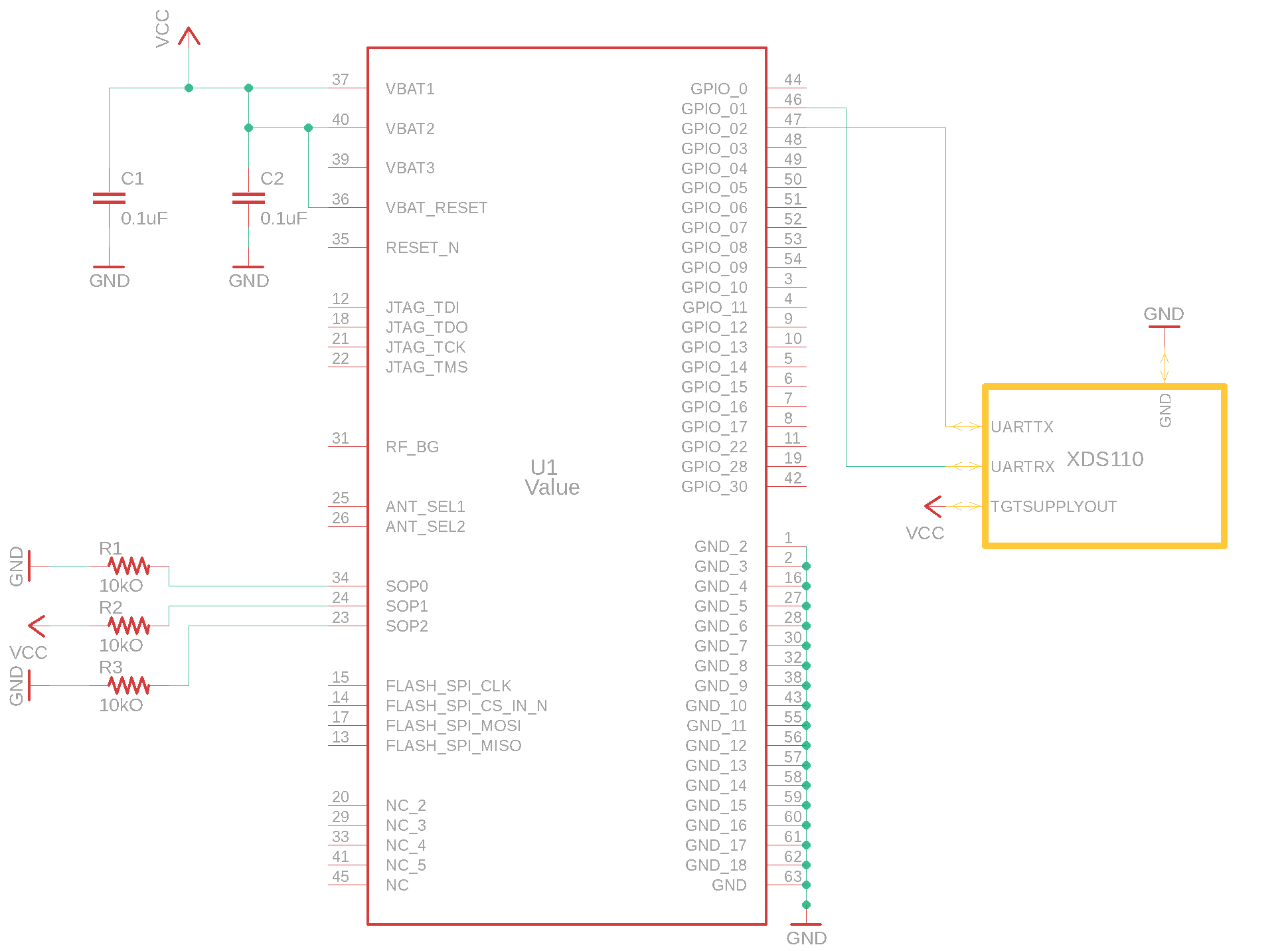
Hello everyone! After successful software development and testing on CC3220SF Launchpad, we are ready to test in on "bare" MCU. We have chosen CC3220MODASF. As programmer, we use XDS110 Debug Probe's AUX ports for UART.. We followed typical connection scheme from data sheet. Here's how it all is connected:

As mentioned in this post GPIO01 and GPIO02 are UART0 TX and RX. Uniflash session is started with following params:

When I try to read memory, green mark appears close to "Cortex_M4_0". And it stucks on Loading. When I click "Erase flash" I have the following output:

[7/16/2018, 4:26:17 PM] [INFO] Cortex_M4_0: GEL Output: Memory Map Initialization Complete
[7/16/2018, 4:26:17 PM] [ERROR] IcePick_C: Error connecting to the target: (Error -267 @ 0x0) The controller could not detect valid target supply. Check target JTAG connection and/or connection setting specifying voltage level. (Emulation package 8.0.27.9)

It would be great for TI to publish some guide describing MCU programming and flashing. Any help would be appreciated.

  • Nikita,

    You mentioned that software development and testing on the LaunchPad was successful. Are you doing anything differently now with Uniflash when trying to flash the device on your custom PCB? When choosing the device on Uniflash's main page, have you tried selecting CC3220SF-LAUNCHXL instead of CC3220SF? If you haven't already, although you are using a module on a custom PCB, try selecting and using the CC3220SF-LAUNCHXL option.

    Also, when building your custom PCB, did you follow the hardware design checklist? If not, download the checklist here and click on the CC3220MOD tab at the bottom of the spreadsheet. Go through the checklist and ensure that your design follows the guideline. The checklist can be downloaded here:

    BR,

    Seong

  • Hi,

    Just a one quick comment which can be elaborated... I hope that Seong will not be angry to me :)

    You have connected module by UART. This is fine to uploading content by Uniflash via Image creator. But at images above you have selected in Uniflash JTAG. And there are two problems:
    - at CC3220 devices is Uniflash used with UART and not with JTAG, cause it not make much sense use JTAG (4w or SWD)
    - you haven't connected JTAG pins (TDI, TDO, TCK, TMS), and from this reason you cannot connect by JTAG

    Jan
  • Haha I always appreciate your help, Jan. Thank you for catching that :)

    Jan is absolutely right, connect your JTAG pins accordingly to use Uniflash's Memory tool.

    BR,
    Seong
  • Now I selected Launchpad on Uniflash's main page. But when I click connect, I get Operation failed: Timeout reading data.

  • Hi,

    Did you restart your board before connection attempt? Also do not forgot that you have very short time window to your connection attempt. In case of usage SOP mode 010 you is really recommanded to have capability for remote restart of CC3220 (as is at CC3220 LP).

    Jan
  • It is really hard to debug this situation, because there are many points of failure. It would be great if you provide specific steps on how to flash CC3220MODA. I have followed hardware design checklist, so everything necessary is present. I also noticed that XDS110's TGTSUPPLYOUT doesn't supply any power. So I connected separate power supply to breadboard and provided GND to XDD110's Auxiliary Breakout PCB. I selected CC3220-LAUNCHX as target device in Uniflash, but when I click "Connect" is says timeout. I would really appreciate your help in this situation. When I finally got this to work, I would write an article on Medium, for example, so anyone else wouldn't spend so much time to program CC3320MODA.
  • Hi,

    How to use Uniflash image creator is well described at www.ti.com/.../swru469 . In case of that you not have manufacturing issue (reflow problem of paste under module is pretty common) I expecting you have problem with that you have select SOP configuration 010 but you don't control reset pin for module from debugger.

    I think you should try this:
    - set SOP to 100 (SOP2=1)
    - restart CC3220
    - instantly connect by Uniflash via UART

    It can be useful if you share photos how you connect your board to debugger. Also you can use your Launchpad instead of usage of XDS110 debug probe. In this case you need disconnect UART from internal CC3220 and connect it to your MOD. This document could be also useful www.ti.com/lit/an/swra568/swra568.pdf (chapter 5.4).

    Jan
  • Hey Nikita,

    Were you able to fix this issue?

    BR,
    Seong
  • Closing this thread. Please start a new thread if you have any other questions.

    Thanks,
    Seong