This thread has been locked.

If you have a related question, please click the "Ask a related question" button in the top right corner. The newly created question will be automatically linked to this question.

Linux: WL1835 FW: R8.7 SP3 test FAILS for RF output power and adaptivity

Other Parts Discussed in Thread: WL1835MOD

Tool/software: Linux

Hello TI.

  Any guider documents for us to pass EN 300 328 2.2.2  RF output power and adaptivity.

  Let me know if any information is necessary.Thanks!

Test failed report as belows:


EN 300 328 2.1.1


DUT Information

Frequencies


WLAN CH 1 (2412 MHz)

WLAN CH 2 (2417 MHz)

WLAN CH 3 (2422 MHz)


WLAN CH 4 (2427 MHz)

WLAN CH 5 (2432 MHz)

WLAN CH 6 (2437 MHz)


WLAN CH 7 (2442 MHz)

WLAN CH 8 (2447 MHz)

WLAN CH 9 (2452 MHz)


WLAN CH 10 (2457 MHz)

WLAN CH 11 (2462 MHz)

WLAN CH 12 (2467 MHz)


WLAN CH 13 (2472 MHz)


Bandwidths


20 MHz (20 MHz)

40 MHz (40 MHz)


Power


20.000 dBm (20 dBm)


Beamforming Gain


20.000 dBm (20 dBm)

0 dB


Gain Tables


20.000 dBm (20 dBm)

Port 1: 3;


DUT Settings


No. of transmission chains

1


Modulation

other


Adaptive

Yes


Short Signaling

Yes


LBT

Yes


Equipment Mode

Load Based


Channel Occupancy Time

18 ms


CCA

15 祍


Medical Device reverse compatibility mode

No


Hardware Setup: WMS Measurements\TS8997


Spectrum Analyzer:

SA FSV 40 (SA FSV 40) @ VISA (ADR TCPIP::192.168.48.148::inst0::instr)


Vector Generator:

VG SMBV100A (VG SMBV100A) @ VISA (ADR TCPIP::192.168.48.149::INST0::INSTR), FW 3.1.19.15-3.50.082.47


Generator:

SMB100A (SMB100A) @ VISA (ADR TCPIP::192.168.48.150::INST0::INSTR), SN 108272, FW Rev 2.21.0, 07/2016, CVI 2015


OSP:

OSP-B157W (OSP-B157W) @ VISA (ADR TCPIP::192.168.48.157::inst0::instr), SN 1527.1144. /, FW 1.23.0.2


Summary

Test

Frequency
(MHz)

Nominal Power
(dBm)

Nominal Bandwidth
(MHz)

RF output power, Duty Cycle, Tx-sequence, Tx-gap

2412.000

20.0

20.000000

Adaptivity

2412.000

20.0

20.000000

RF output power, Duty Cycle, Tx-sequence, Tx-gap

2472.000

20.0

20.000000

Adaptivity

2472.000

20.0

20.000000


(continuation of the "Summary" table from column  4 ...)


Test

Result

RF output power, Duty Cycle, Tx-sequence, Tx-gap

PASS

Adaptivity

FAIL

RF output power, Duty Cycle, Tx-sequence, Tx-gap

not finished

Adaptivity

not finished


RF output power, Duty Cycle, Tx-sequence, Tx-gap (2412 MHz; 20.000 dBm; 20 MHz)


Definition: The RF output power is defined as the mean equivalent isotropic radiated power (e.i.r.p.) of the equipment during a transmission burst.

Duty Cycle is defined as the ratio of the total transmitter 'on'-time to the observation period.

Tx-sequence is defined as a period in time during which a single or multiple transmissions may occur and which shall be followed by a Tx-gap.

Tx-gap is defined as a period in time during which no transmissions occur.

The Medium Utilization (MU) factor is a measure to quantify the amount of resources (Power and Time) used by non-adaptive equipment.


RF Outputpower

Max Burst EIRP
(dBm)

Limit Max
(dBm)

Max Burst RMS
(dBm)

Result

18.8

20.0

15.8

PASS


DutyCycle

DutyCycle
(%)

Limit Max
(%)

Result

17.249

---

PASS


MediumUtilization

MediumUtilization
(%)

Limit Max
(%)

Result

7.865

---

PASS


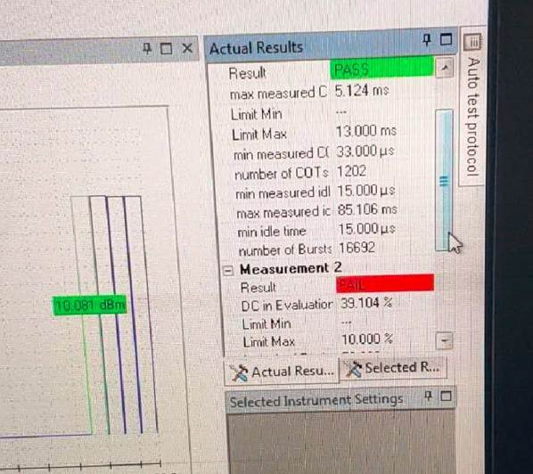
Adaptivity (2412 MHz; 20.000 dBm; 20 MHz)


Summary

Result

Threshold
(dBm)

FAIL

-4.2


Normal Operation

DutyCycle DUT (all ports)
(%)

Monitoring Length
(ms)

COT Max
(ms)

Limit Max
(ms)

COT Min
(ms)

Number of COTs

CCA Time Min
(ms)

CCA Time Max
(ms)

CCA Time Limit Min
(ms)

Result

16.068

10000.000

3.522

13.000

0.029

12852

0.015

26.062

0.015

PASS


Reaction on Interferer

DC in max DC Evaluation Window
(%)

Limit Max
(%)

Result

Length of max DC Evaluation Window
(ms)

Start of max DC Evaluation Window
(ms)

15.948

10.000

FAIL

50.000

35677.340


(continuation of the "Reaction on Interferer" table from column  5 ...)


DC in max DC Evaluation Window
(%)

Stop of max DC Evaluation Window
(ms)

Interferer On
(ms)

Monitoring Offset
(ms)

Monitoring Start
(ms)

15.948

35727.340

1000.000

10.000

1010.000


(continuation of the "Reaction on Interferer" table from column  9 ...)


DC in max DC Evaluation Window
(%)

Monitoring Length
(ms)

15.948

60990.000


Reaction on Blocker

DC in max DC Evaluation Window
(%)

Limit Max
(%)

Result

Length of max DC Evaluation Window
(ms)

Start of max DC Evaluation Window
(ms)

17.616

10.000

FAIL

50.000

37593.820


(continuation of the "Reaction on Blocker" table from column  5 ...)


DC in max DC Evaluation Window
(%)

Stop of max DC Evaluation Window
(ms)

Blocker On
(ms)

Monitoring Start
(ms)

Monitoring Length
(ms)

17.616

37643.820

1000.000

0.000

62000.000


Spectrum Analyzer Normal Operation

Setting

Instrument Value

Target Value

Center Frequency

2.41200 GHz

2.41200 GHz

Span

ZeroSpan

ZeroSpan

RBW

10.000 MHz

<= 20.000 MHz

VBW

10.000 MHz

~ 30.000 MHz

SweepPoints

30001

~ 30001

Sweeptime

10.000 s

10.000 s

Reference Level

-10.000 dBm

-10.000 dBm

Attenuation

10.000 dB

AUTO

Detector

MaxPeak

MaxPeak

SweepCount

1

1

Filter

3 dB

3 dB

Trace Mode

Clear Write

Clear Write

Sweeptype

Sweep

AUTO

Preamp

off

off

Trigger

External

External

Trigger Offset

0.000 ms

0.000 ms


Vector Generator settings for Normal Operation

Setting

Instrument Value

Target Value

RF output

Off

Off


Signal Generator settings for Normal Operation

Setting

Instrument Value

Target Value

RF output

Off

Off


Spectrum Analyzer Reaction on Interferer

Setting

Instrument Value

Target Value

Center Frequency

2.41200 GHz

2.41200 GHz

Span

ZeroSpan

ZeroSpan

RBW

10.000 MHz

<= 20.000 MHz

VBW

10.000 MHz

~ 30.000 MHz

SweepPoints

30001

~ 30001

Sweeptime

62.000 s

62.000 s

Reference Level

10.000 dBm

10.000 dBm

Attenuation

30.000 dB

AUTO

Detector

MaxPeak

MaxPeak

SweepCount

1

1

Filter

3 dB

3 dB

Trace Mode

Clear Write

Clear Write

Sweeptype

Sweep

AUTO

Preamp

off

off

Trigger

External

External

Trigger Offset

1.000 s

1.000 s


Vector Generator settings for Reaction on Interferer

Setting

Instrument Value

Target Value

Frequency

2.41200 GHz

2.41200 GHz

Level

-17.900 dBm

---

Level at DUT

-52.756 dBm

---

System Bandwidth

20.000 MHz

---

Level per MHz

-30.910 dBm/MHz

-30.910 dBm/MHz

Level per MHz at DUT

-65.766 dBm/MHz

-65.766 dBm/MHz

Attenuation

34.856 dB

34.856 dB

RF output

On

On


Signal Generator settings for Reaction on Interferer

Setting

Instrument Value

Target Value

RF output

Off

Off


Spectrum Analyzer Reaction on Blocker

Setting

Instrument Value

Target Value

Center Frequency

2.41200 GHz

2.41200 GHz

Span

ZeroSpan

ZeroSpan

RBW

10.000 MHz

<= 20.000 MHz

VBW

10.000 MHz

~ 30.000 MHz

SweepPoints

30001

~ 30001

Sweeptime

62.000 s

62.000 s

Reference Level

10.000 dBm

10.000 dBm

Attenuation

30.000 dB

AUTO

Detector

MaxPeak

MaxPeak

SweepCount

1

1

Filter

3 dB

3 dB

Trace Mode

Clear Write

Clear Write

Sweeptype

Sweep

AUTO

Preamp

off

off

Trigger

External

External

Trigger Offset

1.000 s

1.000 s


Vector Generator settings for Reaction on Blocker

Setting

Instrument Value

Target Value

Frequency

2.41200 GHz

2.41200 GHz

Level

-17.900 dBm

---

Level at DUT

-52.756 dBm

---

System Bandwidth

20.000 MHz

---

Level per MHz

-30.910 dBm/MHz

-30.910 dBm/MHz

Level per MHz at DUT

-65.766 dBm/MHz

-65.766 dBm/MHz

Attenuation

34.856 dB

34.856 dB

RF output

On

On


Signal Generator settings for Reaction on Blocker

Setting

Instrument Value

Target Value

Frequency

2.48850 GHz

2.48850 GHz

Level

-0.149 dBm

-0.149 dBm

Level at DUT

-35.000 dBm

-35.000 dBm

RF output

On

On


RF output power, Duty Cycle, Tx-sequence, Tx-gap (2472 MHz; 20.000 dBm; 20 MHz)


Test not finished.


Adaptivity (2472 MHz; 20.000 dBm; 20 MHz)


Test not finished.


  • Hi Clark,

    Are you testing the WL1835MOD module or the WL18xx chip down design? Have you modified the .ini file (reference)? If yes, please share your .ini file.

    Best regards,

    Vihang

  • Hi Vihang,

          Thanks for your kind and fast reply,  We have not modified ini file yet,  we would like to check and re-certificate and feedback soon.

    I appreciate!

    BR!

  • Hi Vihang,

    Could you help to confirm how to implement ini file ?
    I refernce to WiLink™ 8 Solutions WiLink8 - wlconf .pdf and config as follows, Any else we should do for ini?

    wlconf -o /lib/firmware/ti-connectivity/wl18xx-conf.bin -I /usr/sbin/wlconf/official_inis/my_ini_file.ini
  • Yes, that is the way to generate the bin file.. Make, sure your ini file has all the needed configuration.

    Thanks
  • Hello Hari,

       I appreciate to your kind help, Recently we using follows ini file that modified EIRP form 7 to 11 dbm (reference to TI certification), but it also failed.

      1, DC in Evaluatior :26%~39% if ini file set EIRP to 11dbm.

      2, certification authority require EIRP >10 dbm  to pass this case.

    -----------------failed detail-------------------------------


    ------------------------------------------ini file-------------------------------------------------------

    #######################################
    ## WL8_1835_C2PC_TI_module_INI ##
    #######################################

    PHY_StandAlone = 00 # Boolean Indicates that there is no MAC cortex active; One of the major impacts is that PHY needs to perform TOP init phase that is done by MAC cortex in operational Mode; 0x0 with Mac; 0x1 no Mac
    PrimaryClockSettingTime = 05 # Time in millisecond from: Rising PRIMARY_CLK_REQ_OUT(9x)/CLK_REQ_OUT(5x) to valid CLK_IN_PRIMARY_P(9x)/CLK_IN_P(5x) from host
    ClockValidOnWakeUp = 00 # [Not Supported] Indicate that when a host wakeup command is issued to the device a valid reference clock is already valid and stable; 0 - Reference clock is not valid (Default) 1 - Reference clock is already valid and stable (Fast Sleep)
    SecondaryClockSettingTime = 05 # 189x Only; Time in millisecond from:Rising SECONDARY_CLK_REQ_OUT to valid CLK_IN_SECONDARY from host (Default 5msec).
    Spare0 = 08 # [Not Supported] TI Internal Usage
    AutoDetect = 00 # [Not Supported] 0x0 - Disabled; 0x1 - Enabled
    Dedicated_FEM = 00 # [Not Supported] Bit 0: no FEM Bit 2..3: vendor options (0: RFMD; 1: TQS; 2: SKWS )
    LowBand_component = 02 # 0x2: 2way or 3way switch. Other values N/A
    LowBand_component_type = 05 # 0x5: One Hot 1.8V. Other values N/A
    HighBand_component = 01 # 0x1: 2way switch. Other values N/A
    HighBand_component_type = 09 # 0x9: One Hot 3V. Other values N/A
    NumberOfAssembledAnt2_4 = 02 # Indicates the active bands and the number of mounted antennas for 2.4GHz;
    NumberOfAssembledAnt5 = 00 # Indicates the active bands and the number of mounted antennas for 5GHz;
    External_PA_DC2DC = 00 # 0: Internal_PA_DC2DC (Default); 1: External_PA_DC2DC
    TCXO_LDO_Voltage = 00 # TCXO LDO 2V5 voltage level select 0x0: 2.5v; 0x1: 2.55v; 0x2: 2.6v;
    XTALItrimVal = 04 # 185x Only; Current trimming for XTAL, (Default) 0x4
    IO_configuration = 01 # Configure drive strength of all non-fixed IO's (Detailed in 18xx_PG2_spinner_xls_sheets.xml) according to the following table:0x0 - 8mA.0x1 - 4mA (default).0x2 - 6mA.0x3 - 2mA
    SDIO_configuration = 00 # [Not Supported] Bit 0: SDIO IB Enable sync; Bit 1: SDIO IB Enable async; Bit 2: SDIO IB Enable BlockMode;
    Settings = 00 # [Not Supported] TI internal - General configuration:Bit 0: N/A ;Bit 1: Enable OCLA over SoC 32K PRAM mode
    RxProfile = 00 # [Not Supported] TI Internal Usage
    PwrLimitReference11ABG = 55 # Single absolute output power value (dBm) that serves as the baseline for all perChanPwrLimitArrABG. Range 0..25.5dBm, Resolution 0.1dB;
    PwrLimitReference11P = 64 # Single absolute output power value (dBm) that serves as the baseline for all perChanPwrLimitArr11P. Range 0..25.5dBm, Resolution 0.1dB;
    Board_Type = 02 # EVB_18XX = 0; DVP_18XX = 1; HDK_18XX = 2; FPGA_18XX = 3; COM8_18XX = 4;
    EnableCLPC = 00 # Boolean that enables the Closed Loop Power Control FW mechanism. In external FEM solution (only 5 GHz), we will monitor and correct the output power based on power detector readings; 0x0 Disabled; 0x1 - Enabled;
    EnableTxLowPwrOnSiSoRdl = 00 # [Not Supported] TI Internal Usage
    Spare1 = 00 # [Not Supported] TI Internal Usage

    PerChanBoMode11ABG = 40 00 04 30 00 00 00 00 00 00 00 00 19
    #PerChanBoMode11ABG represents a 2 bits per channel array (49 channels, hence 13 bytes used). Channels destribution per byte from left side is as follow:
    #Byte0: 1,2,3,4; Byte1: 5,6,7,8; Byte2: 9,10,11,12; Byte3: 13,14,j1,j2; Byte4: j3,j4,j8,j12; Byte5: j16,j34,36,j38; Byte6: 40,j42,44,j46; Byte7: 48,52,56,60; Byte8: 64,100,104,108; Byte9: 112,116,120,124; Byte10: 128,132,136,140; Byte11: 149,153,157,161; Byte12: 165,spare 6 bits for fixed BO cfg
    #BackOff Mode coding:
    # 0 - BO taken from table per rate (default),
    # 1 - Use MAX[fixed BO, Table BO] for 11n & 11g rates only and apply 200nsec TX windowing. fixed BO is set by PerChanBoMode11ABG[103:100] as follow: [103:102] - Set fixed BO for 11n & 11g in 2.4G case with static BW 20M: 0: 7dB; 1: 9dB; 2: 11dB; 3: 13dB; [101:100] - Set fixed BO for 11n & 11g in 2.4G case with static BW 40M: 0: 7dB; 1: 9dB; 2: 11dB; 3: 13dB; Note: 11b packets uses Table BO,
    # 2 - Same as 1
    # 3 - Use MAX[fixed BO, Table BO] for 11n, 11g & 11b rates and apply 200nsec TX windowing. fixed BO is set by PerChanBoMode11ABG[103:98] as follow: [103:102] - Set fixed BO for 11n & 11g in 2.4G case with static BW 20M: 0: 7dB; 1: 9dB; 2: 11dB; 3: 13dB; [101:100] - Set fixed BO for 11n & 11g in 2.4G case with static BW 40M: 0: 7dB; 1: 9dB; 2: 11dB; 3: 13dB; [99:98] - Set fixed BO for 11b: 0: 5dB; 1: 7dB; 2: 9dB; 3: 11dB;

    PerChanBoMode11P = 00 00 00 00
    #PerChanBoMode11P represents a 2 bits per channel array (14 channels, hence 4 bytes used). Channels destribution per byte from left side is as follow:
    #Byte0: 171,172,173,174; Byte1: 175,176,177,178; Byte2: 179,180,181,182; Byte3: 183,184,spare 4 bits for fixed BO cfg
    #BackOff Mode coding:
    # 0 - BO taken from table per rate (default),
    # 1 - Same as 3
    # 2 - Same as 3
    # 3 - Use MAX[fixed BO, Table BO] for 11n, 11a & 11p rates and apply 200nsec TX windowing. fixed BO is set by PerChanBoMode11P[31:28] as follow: [31:30] - Set fixed BO for 11n & 11g in 5G case with static BW 20M: 0: 7dB; 1: 9dB; 2: 11dB; 3: 13dB; [29:28] - Set fixed BO for 11n & 11g in 5G case with static BW 40M: 0: 7dB; 1: 9dB; 2: 11dB; 3: 13dB; Note: PerChanBoMode11P[31:28] is applicable to both 5G band and 11P band

    PinMuxingPlatformOptions = 00 00 # [Not Supported] PinMux options; Byte1 185x (Bit 0: NLE, Bit 1: FM LNA EN); Byte2 189x: (Bit 0: NLE, Bit 1: GPS antenna select, Bit 2: FM LNA EN, Bit 3: GPS PPS OUT, Bit 4: GPS external LNA EN)

    PerChanPwrLimitArr11P = ff ff ff ff ff ff ff
    # PerChanPwrLimitArr11P Limits the TX output power at each of the 11P channels: 14 channels, 1 nibble per channel.
    # PerChanPwrLimitArr11P nibbles: (ch=0),(ch=1),(ch=2),...,(ch=13).
    # In each nibble: Value is in delta from the pwrLimitReferenceP(dB). Range 0dB to 15dB. Resolution: 1dB (0,1,...,15dB)

    SRState = 00 # [Not Supported] Smart Reflex 0-Disabled, 1 -Enabled
    SRF1 = 00 00 00 00 00 00 00 00 00 00 00 00 00 00 00 00 # [Not Supported] Smart Reflex Parameters SRF1 - 1st parameter - num of rows;
    SRF2 = 00 00 00 00 00 00 00 00 00 00 00 00 00 00 00 00 # [Not Supported] Smart Reflex Parameters SRF2 - 2nd parameter - upper limit of the table;
    SRF3 = 00 00 00 00 00 00 00 00 00 00 00 00 00 00 00 00 # [Not Supported] Smart Reflex Parameters SRF3 - All other parameters - Table values;


    # |__CH1___|__CH2___|__CH3___|__CH4___|__CH5___|__CH6___|__CH7___|__CH8___|__CH9___|__CH10__|__CH11__|__CH12__|__CH13__|__CH14__|___j1___|___j2___|___j3___|___j4___|___j8___|__j12___|__j16___|__j34___|___36___|__j38___|___40___|__j42___|___44___|__j46___|___48___|___52___|___56___|___60___|___64___|__100___|__104___|__108___|__112___|__116___|__120___|__124___|__128___|__132___|__136___|__140___|__149___|__153___|__157___|__161___|__165___|_spare__|
    PerChanPwrLimitArr11ABG = ee ee ee ee ee ee ee ee ee ee ee ee ee ee ee ee ee ee ee ee ee ee ee ee ee ee ee ee ee ee ee ee ee ee ee ee ee ee ee FF FF FF ff ff ff ff ff ff ff ff ff ff ff ff ff ff ff ff ff ff ff ff ff ff ff ff ff ff ff ff ff ff ff ff ff ff ff ff ff ff ff ff ff ff ff ff ff ff ff ff ff ff ff ff ff ff ff ff ff ff ff ff ff ff ff ff ff ff ff ff ff ff ff ff ff ff ff ff ff ff ff ff ff ff ff ff ff ff ff ff ff ff ff ff ff ff ff ff ff ff ff ff ff ff ff ff ff ff ff ff

    # PerChanPwrLimitArr11ABG Limits the TX output power at each of the 11ABG channels. 49 channels, 6 nibbles (= 3 bytes) per channel, nibble per each one of 6 modulation types at each channel.
    # PerChanPwrLimitArr11ABG nibbles: (ch=0,mod=0),(ch=0,mod=1),(ch=0,mod=2),...,(ch=0,mod=5),(ch=1,mod=0),...,(ch=48,mod=5).
    # In each nibble: Value is in delta from the pwrLimitReferenceABG(dB). Range is 0dB to 15dB. Resolution: 1dB (0,1,...,15dB)

    PsatMode = 00 # [Not Supported] TI Internal Usage

    #Following three params are For Dynamic Tx Power level control in operational mode STA HP BG only:
    TxPower_level_MaxPower = ff # Max Tx power level ; (Auto mode power setting - 0xff(default mode); Manual mode power settings - 0..30dBm (Default = 0x18 = 24dbm = max power at BG1)
    TxPower_level_MedPower = ff # Medium Tx power level; (Auto mode power setting - 0xff(default mode); Manual mode power settings - 0..30dBm (Default = 0x12 = 18dBm = value for optimal CC) i.e. In case of PerSubBandTxTraceLoss different from 0, TxPower_level_MedPower = 0x12dBm-PerSubBandTxTraceLoss[BG2]
    TxPower_level_LowPower = ff # Low Tx power level ; (Auto mode power setting - 0xff(default mode); Manual mode power settings - 0..30dBm (Default = 0x08 = 8dBm = for best link condition)

    # | BG | A Tx-1 |
    # |B1|B2|A0|A1|A2|A3|A4|A5|A6|A7|
    PerSubBandTxTraceLoss = 10 18 00 00 00 00 00 00 00 00
    # Trace Loss value, 10 bytes (0 - BG1, 1 - BG2, 2..9 - A bands). Byte signed Value in Hex. Range -16..15.875dB, Resolution 0.125dB. This parameter is used in the TX calculations;

    # | BG | A RX-1 | Reserved |
    # |B1|B2|A0|A1|A2|A3|A4|A5|A6|A7| Reserved |
    PerSubBandRxTraceLoss = 10 18 00 00 00 00 00 00 00 00 00 00 00 00 00 00 00 00
    # Trace Loss value, 18 bytes (0 - BG1, 1 - BG2, 2..9 - RX1 A bands, 10..17 - RX2 A bands). Byte signed Value in Hex. Range -16..15.875dB, Resolution 0.125dB. This parameter is used in RX RSSI at ant point report;

    TxRfMargin = 01 # Indicates the commited EVM/Mask margin in dB: 0,1,2,3 or 4. Default = 1;

    TxPower_level_MaxPower_2nd = ff # For Dynamic Tx Power level control in operational mode non STA HP BG, Max Tx power level in dBm Hex val 0..30; (Default = 0x14 - max BG2)
    TxPower_level_MedPower_2nd = ff # For Dynamic Tx Power level control in operational mode non STA HP BG, Medium Tx power level; (Default = 0x0A- med BG2)
    TxPower_level_LowPower_2nd = ff # For Dynamic Tx Power level control in operational mode non STA HP BG, Low Tx power level; (Default = 0x05- low BG2)

  • Hi,

    Can you please help me understand what you mean by " modified EIRP form 7 to 11 dbm (reference to TI certification), but it also failed"
    and "certification authority require EIRP >10 dbm to pass this case."

    There should be no need to modify the .INI file when using the TI module. If you do change the .INI file this violates the modular reuse as you will change the radio settings and can potentially cause other issue , thus requiring re-certification.

    There is no requirement that the EIRP be > 10dBm. The requirement is when the output EIRP power is greater than 10dB then you require adaptivity.

    Note that EIRP power includes the antenna gain. The first think to ensure is that you pass adaptivity. Did you pass this? This requires you to be running in application with iperf and connected to an AP. This should be done conducted and the system calibrated such that the power to the DUT is the calibration plane. Also the AP should be set up for a single test frequency and modulation so it will not change during the test.

    For the interferer signal it is required to be 100% duty cycle (not 99%) or you will fail the test). Can you please confirm that you pass adaptivity for your design?

    Thanks,
    Riz
  • Hi Riz,

    Thanks for your reply. 

    1, Adaptivity certification should be tested with EIRP >10dBm, and we could not find right way to set up.

    2, Certification authority tested 'Adaptivity' follow your explaination, including duty cycle, iperf, single test frequency etc.

    3,We had passed Adaptivity testing with default TI 's certification ini file, but EIRP is 7.222dBm. 

    4,Certification authority and states of product do not allow us to modify antenna gain by hardware. So we try to set EIRP by iw,wlconf,ini etc

       Could you help to  advice what could we set EIRP to pass Adaptivity testing under wireless only station mode?

    I appreciate!

    Best Regards!

  • Hi,

    What modulation are you measuring the 7.222dBm for? According to our datasheet of the module should be well over 10dBm. This indicates to me that there is some other issue. Can you please first provide the following information:

    1) Summary of measured output powers, modulations, and channels.
    2) Do you match our measure CE output powers?
    3) What antenna are you using?

    If the power is below 10dBm, it means adaptivity is not required, but we first need to understand why you are getting the lower power. From your previous data provided it shows that you have a max max burs rms power of 15.8dBm. This is above the 10dB requirement for adaptivity. What modulation is this for? 11b? can you confirm you failed this? For the 7.222dBm that you pass adaptivity for, what is the modulation?

    Thanks,
    Riz
  • Hi Riz,

            1, We used TI's certification ini file to measure  802.11n,and  channel is 2472Mhz, the output power is 7.222dbm. 

            2, CE out powers had tested ok by RTTT tools.

            3, We did not use antenna, Test device will detect ANT.(PS: set +3dbm gain)

           Update information:

           We had passed 2472MHz adaptivity test  when changing AP sending data to local deivce. but not used iperf.

           But, We could not pass adaptivity  in 5G.  I will upload more detials soon

           Thanks for your kind help.

    BR!

  • Hi Riz, 

              Update status of Wifi certification.

    1. We had passed 2.4G Adaptivity test yesterday.

         (Using TI certification ini file,  AP send data to local device(station) but not iperf. That could be passable to Antenna power)

    2. 5G Adaptivity test failed , using 2.4G 's same test case except modified ini file to enable 5G.

        The failed reason is :DC in Evaluatior  > 5% 

        modulation: 802.11n,  channel 36

        Q: How could I set config to stop resend data that seems like reconnected or sniffer to reduce DC in Evaluatior?

             (PS: AP set fixed channel 36, other channel is not available.)

        more detials:

        [How and what we test for certification adaptivity]


    [Channel 36 status,  100% duty cycle interferer signal action on]


    That 's all, Thx.

    BR!   

  • Hi,

    Again first we need to understand why you are measuring low output power. Per our CE report you can see that the output power is much higher that what you are reporting:

    It is still unclear as to why you are measuring 7dB power. Please provide a table similar to the above so we can validate the output power.

    Also from your pictures it is unclear if the set-up is as follows for adaptivity testing:

    I have also attached our CE report for your reference. Please first ensure that you are measuring the correct output power. Note there should be no changes done to the INI file. Also when you are changing to set for 5GHz, you should be using the .conifg to do this and not change the .INI file manually.

    ER741330-02_R01_EN301893_Texas_WL18MODGI_0725.pdf

    Thanks,

    Riz

  • Hi,

    I am closing this thread as it has been taken off line. IF you still need help or is not resolved off-line, please feel free to re-open or repost if the thread is locked.

    Thanks,
    Riz