This thread has been locked.

If you have a related question, please click the "Ask a related question" button in the top right corner. The newly created question will be automatically linked to this question.

CC3220MODA: How to launch and flash firmware of CC3220MODASF12MON

Part Number: CC3220MODA
Other Parts Discussed in Thread: CC3220SF-LAUNCHXL, CC3220SF, CC3220MOD, UNIFLASH, BEEPROG2, TMDSEMU110-U

Hello there!

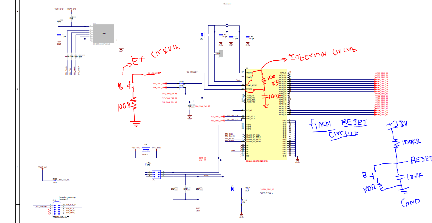
Could you tell me the minimum requirements for CC3220MODASF12MON launching? Which pins should I pull up and pull down with the exception of power and ground pins?

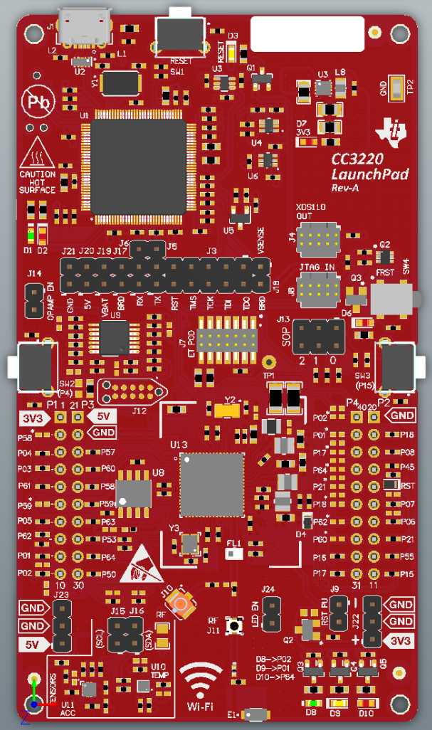
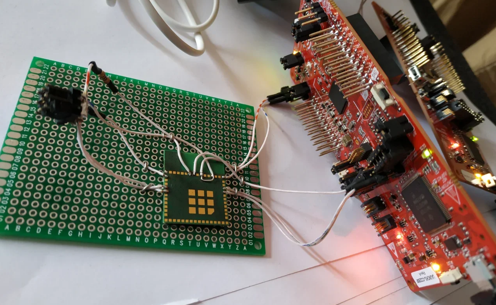
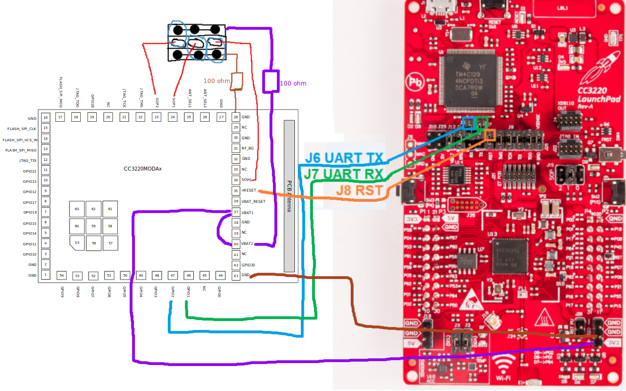
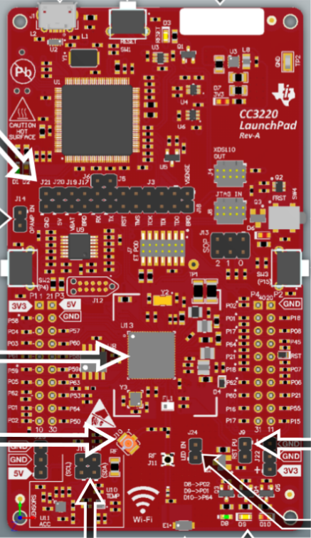
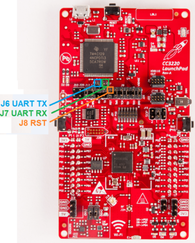
And the second question is about flash firmware. In case of developer board CC3220SF-LAUNCHXL I don't have any problems, but how can I flash firmware into CC3220MODASF12MON? I have read some ways in your guide (www.ti.com/.../swra568.pdf), but I wonder which one is the most easiest to try it with single instance, not mass production. It seems to me that the most easiest way is described in section "5.4 UART Hardware Connection Using the CC3220 LaunchPad". I can't understand your designation on "Figure 4. CC3220 LaunchPad". Because my board has different pins' numbers from shown on the figure there, although these boards are called similarly. Which pins should I really connect? J6, J7, J8 are not the same on these figures, as you can see. I would be very appreciate if someone shares his/her configuration for flash firmware with some description or/and photos. I need a starting point to launch CC3220MODASF12MON with my firmware, which I wrote using CC3220SF-LAUNCHXL.


Thank you in advance.

Best regards,
Roman

  • Hi Roman,

    The CC3220MODASx LaunchPad User's Guide describes the various headers on the board along with the purpose of each.

    Is your CC3220MODASF on a custom board or are you asking about flashing the launchpad? If you're asking about flashing the CC3220SF LaunchPad vs. flashing the CC3220MODASF LAunchpad then it is the same process.

    Thanks,

    Alexis

  • Thank you for your answer, Alexis!

    As I understand, you meant this link http://www.ti.com/lit/ug/swru512/swru512.pdf, because yours doesn't work for me.

    I don't have CC3220MODASF LaunchPad, I only have CC3220SF-LAUNCHXL. And I have a separate module CC3220MODASF12MON without LaunchPad. In the case of LaunchPad, I realize how to flash a firmware throw USB. But I have incomprehension how to flash the firmware of plain module. Later I will use a custom board with a soldered module, but currently, I would like to know how to launch this module to test flashing and launching it without any excess hardware. So I wonder about minimal requirements to launch module and the easiest way to flash it. A photo of the module, about which I talked, you can see below.

    And the second question was about different designations on the same boards, that you can see on screenshots. For example, J6, J7, J8 are in different places of the boards, although these boards are called similarly.

    Best regards,
    Roman

  • Hi Roman,

    The easiest way to program the external serial flash directly will be trough FLASH SPI (Pins 13, 14, 15 and 17). I suppose you could blue wire to these pins to program in order to conduct some preliminary testing without additional hardware as you said.

    For future reference when you are designing your custom board, please refer to our Hardware Design Checklist: www.ti.com/.../swru462


    Thanks,
    Alexis
  • Alexis, thank you for your answer!

    I will try to flash firmware this way. But could you say me what should I fulfill on hardware level to launch this module. Do I need supply power, connect to ground and something else?

    Regards,
    Roman
  • Hi Roman,

    It is not recommended to use the module by itself. If you want to evaluate and test with it, I recommend getting a CC3220MODASF Launchpad: www.ti.com/.../LAUNCHCC3220MODASF

    Thanks,
    Alexis
  • Thanks for your recommendation, but I already have a LaunchPad and program. I asked about a separate module CC3220MODASF12MON without any LaunchPad. Because I need to insert it to another device in the end, and not to debug eternally. We have heard that people had many troubles with the transition from LaunchPad to separate module, so engineers would like to try it now. Could you write to me about how to launch this module without any LaunchPad? I need minimal requirements to launch it and make sure that it works without LaunchPad. Do I need to connect something to launch it besides power supply and ground?

    And what did you mean when you wrote: "It is not recommended to use the module by itself."? For development or production? Or is it better to refuse to use this module at all?

    And could you clarify the meaning of "blue wire" in terms of FLASH SPI programming? ("I suppose you could blue wire to these pins to program...")

    Regards,
    Roman

  • Hi Roman,

    He said that is not recommended to use module without populating to the PCB. Without proper mounting to PCB you may to experience some unexpected behaviour which can be caused by not intended usage. For example you can have issue with overheating in some conditions. Also you can have issue with non prepose of connection of GNDs, etc. Personally I not recommended this use case.

    But if you want still use module without proper populating to PCB you should follow figure 7-1 at datasheet for module. Make sure that you have connected all GND pins properly.

    BTW... troubles are generally with board design for CC32xx QFN not for MOD.

    Jan

  • Jan, thank you for your answer.

    As I understand, the module already has the PCB with an antenna, you can see it on previous photos, it's not a chip. I just want to try flash firmware to this module and launch it without LaunchPad. We will just try once and after that we will produce a proper PCB.
    So, in this case, everything that I need is to connect all GND and VCC pins to launch the module?

    Can you recommend me a SPI programmer to flash a firmware? I have several, but I don't know which chip I should select (see the screnshoot below). Perhaps you can share with me a specific SPI programmer, which can work with CC3220MOD and CC3235MOD.


    And what does "blue wire" mean in terms of FLASH SPI programming?

    Best regards,
    Roman

  • Hi Roman,

    CC3220MOD can be programmed by UART from Uniflash. But if you want program SPI flash directly via pins, you need to use programmer with capability to program SPI flash MX25R3235F.

    If I rememberer properly some older thread, one of tested SPI flash programmers was Cheetah from http://www.totalphase.com or BeeProg2/3 from http://www.elnec.com

    Jan
  • Hi, Jan!

    Thank you for the recommended SPI programmer, but they cost too much to just test. So I will try them later when I will be sure that everything works or if other methods don't work.

    So, what do I need in case of UART programming? I have CC3220MODASF12MON and CC3220SF-LAUNCHXL. Is it enough or I need to use XDS110 (something like TMDSEMU110-U)? Then if to back to my initial question, I wondered about "5.4 UART Hardware Connection Using the CC3220 LaunchPad". But I faced some difficulties with designations. It seems that the same named CC3220 LaunchPads have different designations. "Figure 4. CC3220 LaunchPad" in the guide (www.ti.com/.../swra568.pdf) has other jumpers' numbers than my board. I don't know who to believe. So I would like to clarify on using this method, the actual jumpers and pins, which I need to connect from the LauchPad to the module (LGA, not QFN).

    According to the table "Table4-1. ModulePin Attributes" from www.ti.com/.../cc3220mod.pdf and Pin Diagrams:

    • Pin 55 (UART1_TX) on CC3220SF relates to Pin 46 (GPIO1) on CC3220MODAx
    • Pin 57 (UART1_RX) on CC3220SF relates to Pin 47 (GPIO2) on CC3220MODAx
    • Pin 32 (nRESET) on CC3220SF relates to Pin 35 (nRESET) on CC3220MODAx
    • Pin 35 (SOP0) on CC3220SF relates to Pin 34 (SOP0) on CC3220MODAx
    • Pin 34 (SOP1) on CC3220SF relates to Pin 24 (SOP1) on CC3220MODAx
    • Pin 21 (SOP2) on CC3220SF relates to Pin 23 (SOP2) on CC3220MODAx


    Am I right? I use the module CC3220MODAx, so I need to rely on the related Pins, and not for CC3220 (QFN) guide www.ti.com/.../swra568.pdf, don't I?
    But which jumpers should I use on CC3220SF-LAUNCHXL? I don't know, because my board CC3220SF-LAUNCHXL has other Pin designations from this guide www.ti.com/.../swra568.pdf. I have Pin designations on CC3220SF-LAUNCHXL like on the screenshot below.


    Regards,
    Roman

  • Hi Roman,

    Programming by Uniflash can be done via any kind of UART to USB converter with capability of 921600bd. That means you can use something like FT232RL or CC3220SF LaunchPad. Choice is up to you. In your case is usage of CC3220SF-LAUNCHXL fine.

    I agree that image at fig-4 is pretty weird. It seems that board is marked Rev-A (production version of board) but silkscreen is from pre-production board and contains pre-production silicone (XCC3220 chip). But this is not important. At this figure are marked right connection points (blue, green, orange).

    Inside module is integrated QFN chip. But pin mapping is different. That means MOD pins numbers != QFN pin number. For hardware connection you need to use pin numbers from MOD datasheet.

    Before you connect your module to Vcc please read this design checklist ( www.ti.com/.../swru462 ). For example SOP lines need to have current limiting resistors, etc.

    Jan
  • Hi, Jan!

    Thank you for your assist! I had tried to program a CC3220MODASF12MON module using UART to USB converter PL2303 and through CC3220SF-LAUNCHXL, but nothing has worked out. In the case of PL2303, Uniflash doesn't detect any devices. In the case of CC3220SF-LAUNCHXL, Uniflash detects something and I can read target memory, load firmware from CCS, but indeed it is connected to CC3220SF-LAUNCHXL, not to the CC3220MODASF12MON module. So I read target memory from and load firmware to intermediate CC3220SF-LAUNCHXL, and not to CC3220MODASF12MON module. I don't know, perhaps we have connected something wrong, but everything seems okay. But Uniflash doesn't detect the CC3220MODASF12MON module, which I need to program. Could someone reveal his/her way to flash firmware through UART connection? Because I don't know what is wrong.


    I will be extremely appreciated for help!

    Regards,
    Roman

  • Hi Roman,

    Sorry, I am not able say what can be wrong in your case. It seems that you not have connected all required pads at module (all GND pads). From your picture is not obvious how your module is connected to LaunchPad. Maybe you have exchanged RX/TX lines. Maybe issue is not connected GNDs, maybe you not have properly connected reset pin, who knows....

    Your communication with CC3220 chip is possible from CCS, because you still have connected JTAG jumpers (TDO, TDO, TCK, TMS).

    In case of you want to use 3rd party USB to UART converter, you need to use Uniflash CLI. For usage of Uniflash GUI is mandatory to use XDS110 from LaunchPad. For proper function of Uniflash GUI is control of reset signal mandatory. And this is not possible via 3rd party USB to UART converter like yours PL2303.

    Jan

  • Many thanks, Jan!

    We rang-out all GND pads using a multimeter and it seems that all of them are continuous. Do we need to connect them additionally?

    I tried to depict our connections, but it seems that we really mixed up RX/TX lines. Can you prompt us, do we need to swap them?

    And can you say, are other wires correctly connected or not?

    And in case of correct configuration, what will I see in Uniflash GUI, when push Detect button? Should I see CC3220MODASF12MON or CC3220SF-LAUNCHXL?


    Best regards,
    Roman

  • Hi Roman,

    I am not able to confirm, if is absolutely mandatory to be all GND pins connected.

    From my point of view your connection looks OK including UART connection (GPIO_02 to J6, GPIO_1 to J5)

    No. Not it is not about detect button. But about ability to connect by Uniflash via UART. You need to be able connect as is lustrated at chapter 6.4 in www.ti.com/.../swru469

    Jan
  • Hi Jan,Roman,

    VBAT_RESET must be pulled up to VCC_3.3V.

    Jan my understanding is correct see image ?

    Vasu

  • Hi Vasu,

    Thank you for your comment.

    Connection of VBAT_RESET pin is described at chapter 4.2 in CC3220MOD datasheet.

    In case of connection to CC3220 LaunchPad is this additional pull-up resistor not mandatory, because it is at LaunchPad already (see schematic  of LaunchPad and 100k resistor R17). But at other hand. If you connect additional 100k resistor, it should not happen anything wrong. Only power consumption will be slightly higher.

    Jan

  • Hi Jan,
    Thank you for your clarification,
    I checked with schematic you are right.
    If we go for module with own pcb VBAT_RESET must be pulled up to VCC correct ?

    Vasu
  • Hi Vasu,

    Yes, is should be. Unless you have nRESET controlled by some other external circuits with own pull-up.

    Jan

  • Thank you jan

    Vasu
  • I want to give thanks to you, Jan! You have helped me to resolve my troubles with flashing firmware to a module. It seems that I figured out with this process and now I am able to flash module and launch it. Thank you very much!

    Sincerely,
    Roman
  • Hi Roman,

    Great. I am just curious, what was wrong?

    Jan