This thread has been locked.

If you have a related question, please click the "Ask a related question" button in the top right corner. The newly created question will be automatically linked to this question.

LAUNCHCC3220MODASF: Custom board module heat

Part Number: LAUNCHCC3220MODASF
Other Parts Discussed in Thread: CC3220SF, CC3220MOD, TPS62160

We developed our custom board(cc3220modasf) time being we attached only module.

CC3220 Launched pad(3.3v) connected to our custom board power supply.

Our custom board working fine i can able to debug and flash but module heating after some time module is off automatically after power off and power on power working fine.

why module is heading ?

Vasu

  • Hi,

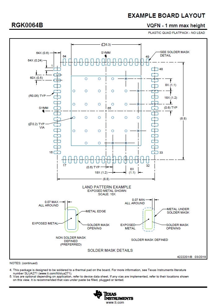
    Did you Solder the Paddle (Thermal Pad underneath the Chip) to the Board? If not , heat will not transfer from the chip to the Board and it may heat up the chip.

    Please check your soldering on the Board.

    The following is the CC3220 Example Layout with Gnd Vias on the Paddle ( Thermal Pad underneath the Chip).

    Thanks,

    PM

  • Hi PM,

    Our custom board containing cc3220modasf .
    Are you telling cc3220sf ic ?
    we soldered cc3220modasf module directly to our custom pcb.
    Module is heating after that automatically off.
    what is that Thermal Pad ?

    Vasu
  • Hi,

    Sorry about that. Yes, my earlier post  (Thermal Pad for CC3220SF) was for CC3220SF. Please ignore it.

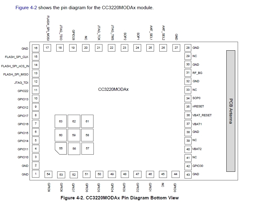
    Did you Solder the Thermal Pads 55 thru 63 of the Module to your PCB? Good thermal contact is required from your PCB to these Pads for Heat Transfer.

    The following is the Pin out for CC3220MODAx for your ready reference.

    What is the Vbat Voltage? Did you check the Vbat Voltage?

    Did you check the Current consumption? Please refer to Table 5.4 of the data sheet for current consumption specs.

    If it draws more than specified then their might be an issue with the Module.

    How many Boards you tested? Does all the boards exhibit the same problem?

    Thanks,

    PM

    Thanks,


  • Hi Vasu,

    In the addition to answer from PM. CC3220 module does not heat much generally in normal operation conditions. Measurement of current consumption is crucial to determine issue as was pointed by PM. Are you able quantify how much is your module heating (e.g. image from thermal camera)?

    - According my experiences are MOD with CC32xx very reliable. But very common is manufacturing issue at customer side especially at prototypes. Problem with soldering (paste reflow) was many times reported at this forum. Such kind of manufacturing issue can increase current consumption and heat production.
    - Usage module out of operation conditions (higher Vbat, high current flow from i/o pins, usage TTL devices at i/o pins) will significantly increase heating.
    - Module damaged by ESD can produces significant heat as well.

    Jan
  • Hi Jan, PM,

    Thank You for your response,

    PM :

     Thermal Pads 55 thru 63 of the Module to your PCB ?

           Yeah it's connected and soldered to PCB

     Power Source ?

         External variable power supply adjusted with 3.3v, 450 mA (after that also heating)  

     How many board tested ?

         Time being i tested with two boards same issue.

    Jan:

       PCB only soldered with module and leds, and flash uart0 pull up, sop.

       We don't have thermal camera but even 1min also you not possible to touch continuously that much heat coming.

       Module soldering we gave some third party company.

       what is this ESD can produces significant heat ?

    I attached module with PCB image.

    What is the issue ?

    How to solve this issue ?

    Vasu

  • Hi Vasu,

    You have something wrong deficiently. 450mA for such usage is too much. My own hardware with CC3220MOD many other chips have consumption approximately 100mA. I use CC3220 always on-power policy and in power source LDO (5V to 3.3V). If your module is so hot to not be able touch, this is wrong as well.

    From my point of view you have signification issue with your design or manufacturing (soldering). According my experiences you may to have problem with:
    - wrong PCB design (PCB manufacturing issue is unlikely)
    - problem with external components (wrong values of SOP resistors)
    - manufacturing issue (short circuits under module caused by wrong soldering)
    - damaged module (by ESD or by wrong handling)

    From my point of view will be best approach use thermal camera to determine what is causing heat and X-ray to soldering inspection.

    Jan

  • Hi Jan,
    Thank you for your response,

    I tested with three board.
    Board one :
    Somewhere shorting.
    Board two :
    If i gave (3.3v, 350mA) that time only started working(module taking 290-300mA) but heat producing more.
    If i give below 300mA its not working.
    may be this issue on PCB soldering with module ?
    Board Three:
    I gave (3.3v, 100mA) PCB containing module and some other chip its taking only (48-50mA).
    module not producing any heat.
    working fine.

    issue on module soldering ?
    or any other issue ?

    We having LDO TPS62160 how to design 3.3v 100mA do you have any reference design ?
    I checked with WEBENCH but it giving (3.3v ,1A) output.

    Vasu
  • Hi Vasu,

    From my point of view it looks as soldering issue (because you have more boards with different behaviour). You can also have problem with board layout for soldering pads under module.

    I am not able help you with selecting right LDO for your application. But LDO with 1A max. current looks reasonable. Your power source need to be able provide current for RF calibration (450mA at 3.3V for 24ms).

    Jan

  • Hi,

    I agree with Jan, you might be having a Soldering issue on your boards. Avoid Manual soldering.

    If you need help with TPS62160 design, I suggest to create a separate thread for that and post it then the Product expert will respond to your post.

    Thanks,
    PM