This thread has been locked.
If you have a related question, please click the "Ask a related question" button in the top right corner. The newly created question will be automatically linked to this question.
Hi,
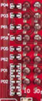
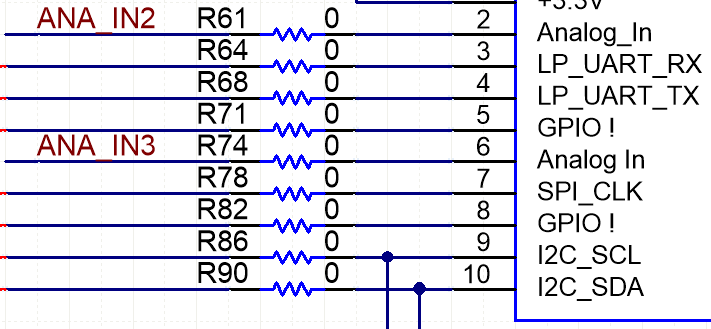
I've been reading through the CC32235MODSFD laundhpad user guide from http://www.ti.com/lit/ug/swru548/swru548.pdf, but I couldn't find an explanation of the highlighted components below. Can anyone provide an explanation of what each of these components do on the launchpad?
Hi,
Please see design files (schematic) for CC3235MOD LaunchPad.
Jan
Hi Jack,
I am little bit confused from your questions, but anyway...
Reason of all 0 orh resistors is very simple. It allow to you disconnect trace by unsoldering of the resistor. From this reason you don't need scratch a PCB trace for disconnecting. What may not be even possible at four layers board. For example by disconnecting resistor R82 and populating resistor R80 you can move P62_GPIO_07 from P1 to P2 connector.
Path LP_RESET_OUT is a output pin of RESET signal from LuanchPad. Schottky diode D6 is here to do not allow external device connected to LP_RESET_OUT change state of CC_nRESET. When LP_RESET_OUT is held at low using external device it not affect state of CC_nRESET line.
Jan