This thread has been locked.

If you have a related question, please click the "Ask a related question" button in the top right corner. The newly created question will be automatically linked to this question.

CC3220MOD: CC3220MOD Schematic and Gerber for review

Part Number: CC3220MOD
Other Parts Discussed in Thread: CC3120MOD

Hi TI Champs 

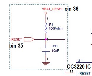
We have designed a board for CC3220mod Module and have followed the Guidelines mentioned in the datasheet.

Please find attached the schematic and Gerber for the same.

Request to kindly review the same.

Best Regards

Dattaguru

CC3220MOD_BEE Schematic.pdf

  • Hi,

    After a quick look there is a few things.

    • why you have 10p capacitor at RF_BG output?
    • why you use RF filter? RF filter is inside module already. From this reason is not mandatory external filter.
    • pull-down resistors at SOP lines are not mandatory (pull-down resistors are inside module already)
    • it is expected that you will need to add pull-up at RX line (but this is not big deal because you have DNP pull-up positions)
    • if it is possible, do not connect pin 52 (GPIO_07) of MOD to any external hardware. Because this is is used for a NWP log for a diagnostic of issues. it may to be reasonable add this pin some headers/via. Just for a case if you will need capture this log.
    • it looks that you want to use additional 2.4GHz radio device at your board. You will need to properly design your board to avoid interferences between your ZigBee and Wifi. Additional option my to be use CC3235MOD which have capability for co-existence for other 2.4GHz radios. But I am not sure if this feature is supported by XBEE.

    Design checklist for CC3220 devices you find here. Please see cheet CC3220MODx.

    Additional comment may to provide you guys from TI.

    Jan

  • Dattaguru,

    Please provide the gerbers as well. I've reviewed the schematic. See my feedback below:

    1. The matching network are the same values as our reference design. These will vary on your own board, so please perform antenna matching to ensure 50 ohm impedance. 
    2. There is a 100k resistor and 10nF cap RC network internal to the module that is tied to the module pins 35 and 36 and the CC3220 IC's reset pin 32 (see below). So you can eliminate R19 and C7, tie pin 36 to VCC, and keep the switch connected to pin35. 
    3. As Jan already mentioned, there are pull down resistors tied to the SOP pins internal to the module, so you can remove R1, R2, and R3. R4 is still required to pull the SOP pins high.
    4. Add 100k pull up resistors to pins 46 and 47. I see there are already provisions for this, as Jan said.
    5. As Jan mentioned, there is already a filter internal to the module.
    6. Jan's comment on pin52 actually applies to the CC3120MOD. You can use this pin as a GPIO or UART. 

    BR,

    Seong

  • Hi Seong,

    No. I think you not understand want I want to say about NWP log pins.

    From schematic it looks that he have a few unused pins at module. In this case I think is a pretty good idea to not use pin_52 (QFN pin_62) in application and reserve this pin for NWP_log. Just for a case.

    Just imagine. He have a problem and he need to capture NWP log but pin_52 is already used in application. In this case he will a issue. In case of pin_52 will be connected to pad near to module, obtaining NWP log will be pretty easy.

    Jan

  • Thank you, Jan.

    Dattaguru,

    If you can use another pin to replace pin 62, I would follow Jan's recommendation. More information on capturing NWP logs can be found here: https://processors.wiki.ti.com/index.php/CC3120_&_CC3220_Capture_NWP_Logs

    BR,

    Seong