This thread has been locked.

If you have a related question, please click the "Ask a related question" button in the top right corner. The newly created question will be automatically linked to this question.

CCS/CC3200MOD: CC3200MOD I2C on Pins 5 & 6

Part Number: CC3200MOD
Other Parts Discussed in Thread: CC3200

Tool/software: Code Composer Studio

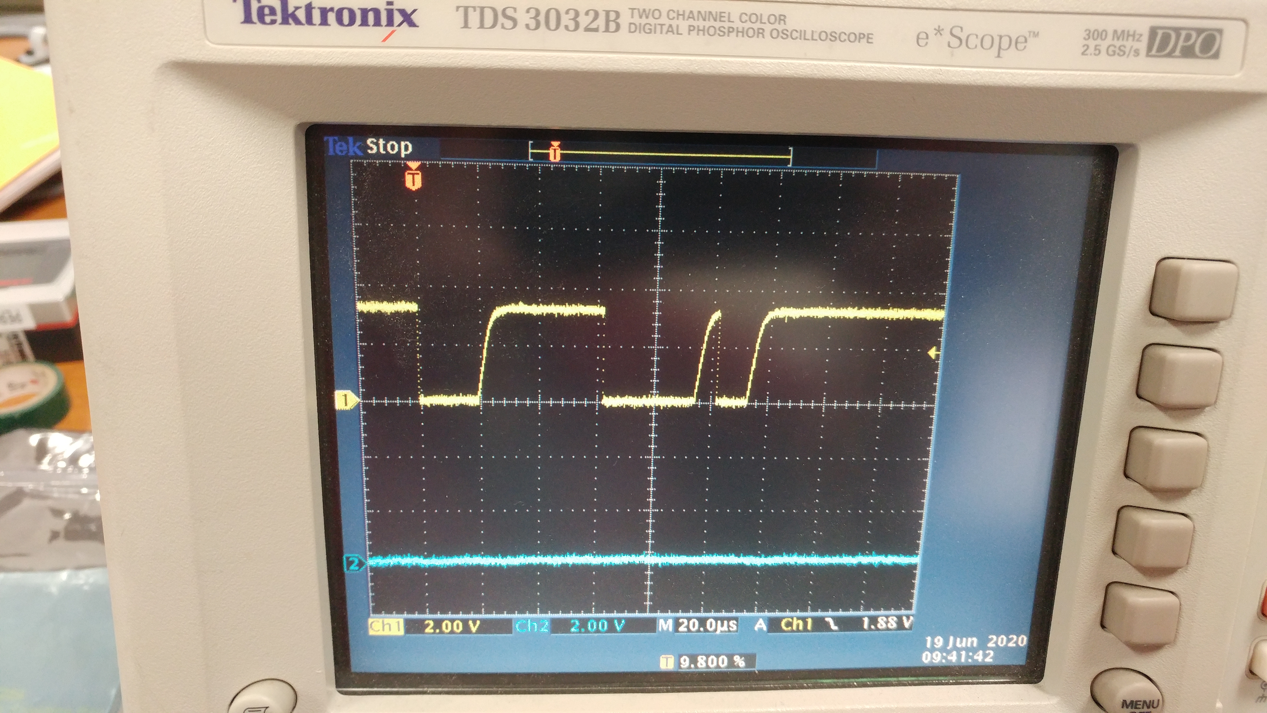
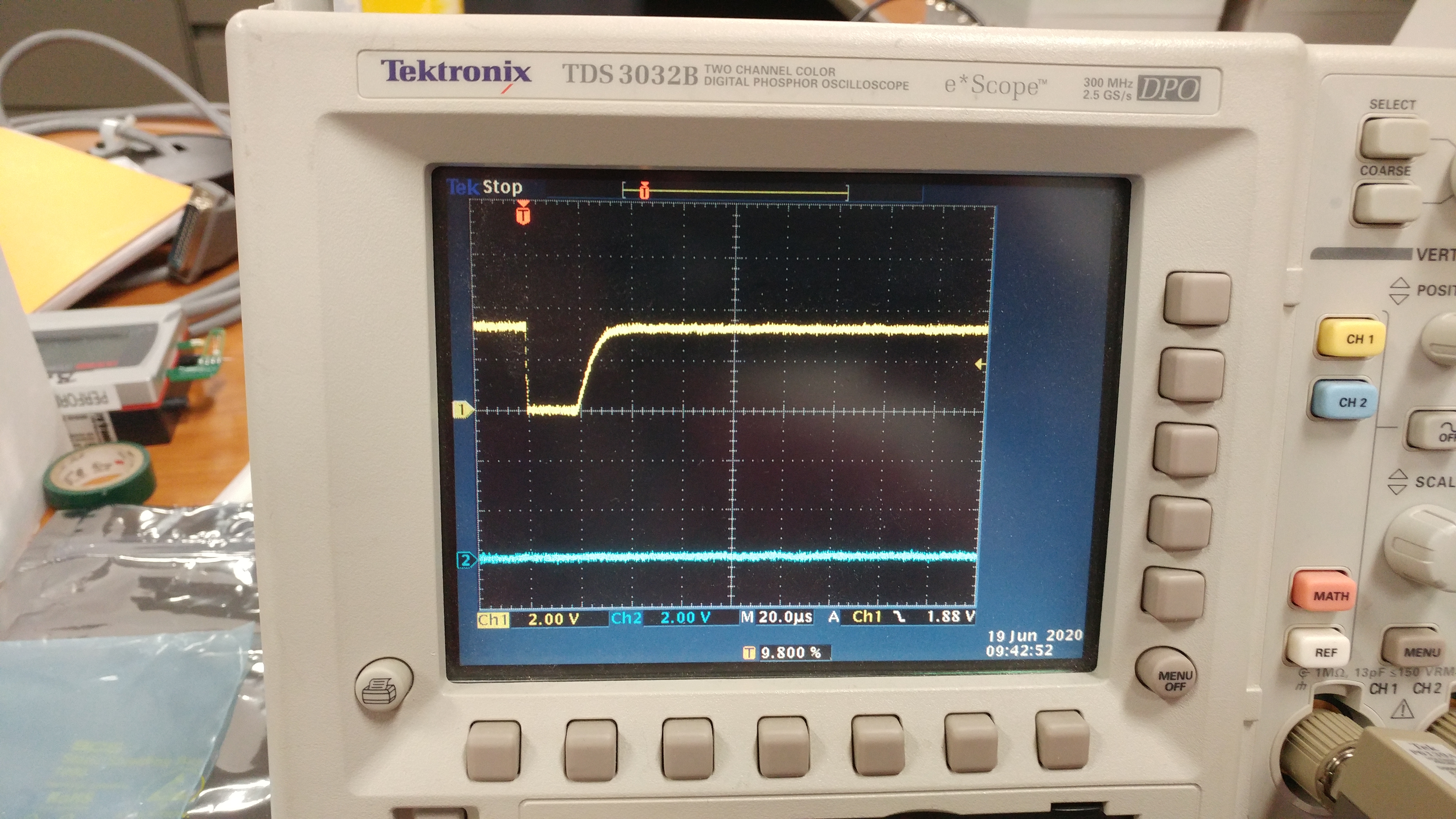
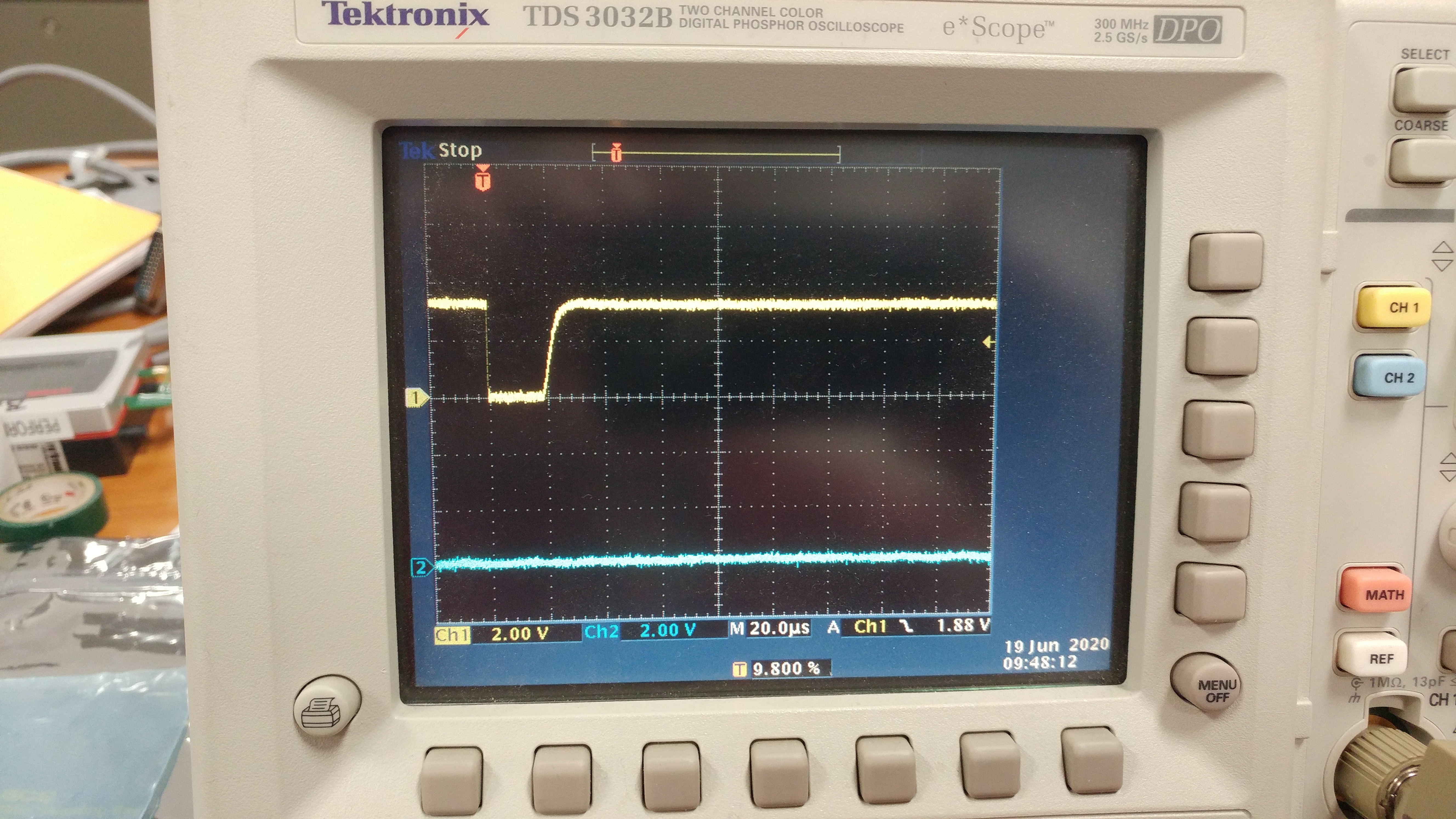
I'm move off the Lanchpad to the Module and need to move the I2C function from Pins 1 & 2 to Pins 5 & 6.  I've made the changes in the pin_mux_config.c, CC3200_LAUNCHXL.c and CC3200_LAUNCHXL.h.  Everything complies and loads, but I get a single pulse out of pin 5 and then the system appears to lockup.  I've attached the file.  The pin_mux file has all the pin assignments for the planned application.  I'm sure I've missed something simple.

Thanks,

KevinCC3200Mode Pin files.zip 

  • Hey Kevin,

    I checked your pin_mux file and it looks fine.

    If you try using pins 3&4 or 16&17 do you see the same behavior?

    Regards,
    Paul

  • Hey Paul,

    Sorry for the time lag.  I had to add some UART stuff since there is no debug port on the board.  What I found it the I2C port appears to initialize (at least the handle is not coming back null from the I2C_open call), but an error is generated when calling one of my send data commands. This seems to be the case regardless of which set of pins I initialize.  I haven't had a chance to put a scope on all the pins to look for the com traffic, hopefully Friday. It may be a connection issue between the I2C device and the processor.

    Below is the single command send macro,which works on the Launchpad .  I'll update you after I check the HW closer.

    Regards,

    Kevin

    int I2CSendCom(I2C_Handle handle, char data)
    {
    uint8_t txBuffer[8]; //Array for the transmit data
    uint8_t rxBuffer[8]; //Array for received data
    I2C_Transaction i2cTransaction; //i2c Tx/Rx structures

    int rp = -1;
    txBuffer[0] = 0x00; // byte to send after slave address
    txBuffer[1] = data; // byte to send after slave address
    i2cTransaction.slaveAddress = Display_ADDR; //SHT85 sensor address
    i2cTransaction.writeBuf = txBuffer; //write the Tx buffer to the slave
    i2cTransaction.writeCount = 2; //number of byte to Tx
    i2cTransaction.readBuf = rxBuffer; //read the RX buffer
    i2cTransaction.readCount = 0; //number of bytes to read from Rx buffer
    if(I2C_transfer(handle, &i2cTransaction))
    {
    rp = 0;
    }
    char output[9];
    sprintf(output,"SC rp %d\n", rp);
    UART_write(uart,output,sizeof(output));

    return rp;
    }

  • Update.  I compiled the i2ctmp006_CC3200_LAUNCHXL_TI_CC3200 example to send a signal command to the display on the I2C bus.  The display and the pull up resistors have been removed from GIO14 & 15 to make the conditions on all pins the same, making the return to the 3.3V state slowed.

    I tested the GPIO10 & 11 (Launchpad pair), GPIO14 & 15 (Desired pair) and the TDI, TDO pair.  I could not test the GPIO12 & 13 pair, because GPIO13 is used in the design as an input and to isolate it would require removal of half a dozen components.

    What I saw on the scope is the following.  The SCL (clock) single is present on all 3 pairs tested.

    The SDA (data) single on GPIO11 shows the start pulse and the command bit + device address pattern, but the data byte is not sent, I assume because the device did not ACK after the address byte.

    GPIO15 & the TDO pins show the start pulse ONLY, no address byte is seem.  I've attached the SDA scope traces.  pin_02 = GPIO11, pin_06 = GPIO15, pin_17 = TDO.  GPIO15 exhibited the same with the display and pulls in place.

    Pin_02

    Pin_06

    Pin_17

    Late Friday further update:  I hand modified the board to use the module's GPIO10 & 11 for the I2C port, as the Launchpad does, and was able to successfully communicate and control the display.  I can modify the design to use these pins, but I would still like to know why the the other pin pairs don't work.  For layout reasons I would like to save GPIO10 & 11 for future SDCARD expansion. 

    Regards,

    Kevin


  • Hey Kevin,

    Sorry for the delayed response. I'm glad you you were able to get unblocked using the launchpad default pins.

    Unfortunately, I'm not familiar with the i2ctmp006_CC3200_LAUNCHXL_TI_CC3200 example you mentioned. Where did you get that example from?

    Using the i2c_demo example, I was able to verify that I2C communication works when connected to pins 5 and 6 (GPIO 14 and 15). The only edits I made to get the example working were in pinmux.c. Here are the changes I made: 

    PinModeSet(PIN_01,PIN_MODE_0);
    MAP_PinTypeI2C(PIN_05, PIN_MODE_5);
    
    PinModeSet(PIN_02,PIN_MODE_0);
    MAP_PinTypeI2C(PIN_06, PIN_MODE_5);

    Could you try the i2c_demo example from the latest CC3200 SDK 1.5.0 with the above changes? Hopefully we can rule out any hardware issue.

    Regards,
    Paul