This thread has been locked.

If you have a related question, please click the "Ask a related question" button in the top right corner. The newly created question will be automatically linked to this question.

CC3220S: More Current consumption of CC3220S in LPDS mode

Part Number: CC3220S
Other Parts Discussed in Thread: UNIFLASH, SYSCONFIG

Hi Team

I am facing issue of high current consumption in LPDS mode of CC3220S.

After LPDS mode on our custom firmware it is going with 18~24mA continuous current while running with Ti LPDS example code it is taking only 287uA.

We have built our code on cloud OTA example and have only one thread apart from cloud_ota thread.

Testing has been performed on Ti Launchpad. So, here i am sure there are something which we are missing in firware.

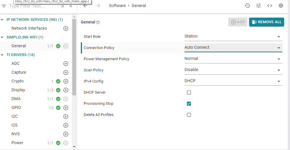
Can you please help me what setting or configurations are we missing?

  • Sumit,

    Are you enabling the TI-RTOS power policy by calling enablePolicy()?

    BR,

    Vince 

  • Hi Vince,

    Yes we are enabling the power policy.

    One thing to note here is that we have built our code over the cloud OTA example. Here we have another observation that each thread needs to be put to sleep individually. Is this right?

    Regards

    Ravija

  • Ravija,

    That is correct. If you find a task is looping but not doing anything, try first to add a sleep(10) to put the task asleep for 10 seconds. if you find the culprit, then i would start thinking about a better way to put that task asleep using semaphores or mailboxes.

    BR,

    Vince 

  • Hi Vince,

    Thanks for the quick reply.

    So we tried putting the OTA thread to sleep and it did save us about 5mA of current.

    Can you give us more pointers as to what could be still consuming power?

    Our device still consumes ~14mA current in the LPDS mode. We get the same results even when we tested our code on the launchpad without anything connected, so we think that there shouldn't be a peripheral leaking current.

    Our LPDS settings are as below:

    • Power
       
    • Enable Policy N
      Policy Function
      PowerCC32XX_sleepPolicy
      Policy Init Function
      PowerCC32XX_initPolicy
      Enter LPDS Hook Function
      -
      Resume LPDS Hook Function
      -
      Enable Network Wakeup LPDS                   N
      Keep Debug Active During LPDS N
      Enable GPIO Wakeup LPDS Y
      Wakeup GPIO Source LPDS
      GPIO4
      Wakeup GPIO Type LPDS
      RISE_EDGE
      Wakeup GPIO LPDS Function
      gpio_callback
      Wakeup GPIO LPDS Function Arg
      0
      Enable GPIO Wakeup Shutdown Y
      Wakeup GPIO Source Shutdown
      GPIO4
      Wakeup GPIO Type Shutdown
      RISE_EDGE
      RAM Retention Mask LPDS
      SRAM_COL_1, +3 more
      IO Retention Shutdown
      GRP_1

      Park Pins

      Pin Park States

      Change All Pins
      Default
      PIN01
      WEAK_PULL_DOWN_STD
      PIN02
      WEAK_PULL_DOWN_STD
      PIN03
      DONT_PARK
      PIN04
      DONT_PARK
      PIN05
      WEAK_PULL_DOWN_STD
      PIN06
      WEAK_PULL_DOWN_STD
      PIN07
      WEAK_PULL_DOWN_STD
      PIN08
      WEAK_PULL_DOWN_STD
      PIN13
      WEAK_PULL_DOWN_STD
      PIN15
      DONT_PARK
      PIN16
      WEAK_PULL_DOWN_STD
      PIN17
      WEAK_PULL_DOWN_STD
      PIN18
      WEAK_PULL_DOWN_STD
      PIN19
      WEAK_PULL_DOWN_STD
      PIN20
      WEAK_PULL_DOWN_STD
      PIN21
      WEAK_PULL_DOWN_STD
      PIN29
      WEAK_PULL_DOWN_STD
      PIN30
      WEAK_PULL_DOWN_STD
      PIN45
      WEAK_PULL_DOWN_STD
      PIN50
      DRIVE_HIGH
      PIN52
      WEAK_PULL_DOWN_STD
      PIN53
      WEAK_PULL_DOWN_STD
      PIN55
      WEAK_PULL_UP_STD
      PIN57
      WEAK_PULL_UP_STD
      PIN58
      DONT_PARK
      PIN59
      DONT_PARK
      PIN60
      WEAK_PULL_DOWN_STD
      PIN61
      WEAK_PULL_DOWN_STD
      PIN62
      DONT_PARK
      PIN63
      WEAK_PULL_DOWN_STD
      PIN64
      WEAK_PULL_DOWN_STD

      We tried with the default pin configuration (all pins pulled down except pin 55 and 57 being pullled up) and also with a custom pin config where we changed some of the pins as per their use case and left many others as it is.

      What else can we check as per your suggestion?

      Regards

      Ravija

  • Ravija,

    If you are using TI RTOS, you should be able to use the RTOS Viewer to see what tasks are active and what are sleeping. I would check each task and make sure they are put to sleep. Secondly, when you flash the device with Uniflash, in the settings you can disable mdns and the internal HTTP server. This should save you some power if these features aren't needed.

    Lastly if you have a capture of the high power consumption, I help diagnose by looking at the profile. If it's short spikes of current ~50mA, thats us going into recieve mode - ~150+mA and its transmitting - ~15mA the MCU is likely not in LPDS.

    BR,

    Vince

  • Hello Vince,

    My apologies for replying late, as I was stuck with some urgent release work and could not try out your suggestions earlier.

    I tried turning of the internal httpserver by using the following command :

    sl_NetAppStop(SL_NETAPP_HTTP_SERVER_ID);

    and reset the server right before the provisioning starts after the device resets (Our code is based on the Cloud_OTA example)

    sl_NetAppStop(SL_NETAPP_HTTP_SERVER_ID); /*Turn off internal server to save on power consumption*/
    sl_NetAppStart(SL_NETAPP_HTTP_SERVER_ID);

    I am not sure if the MDNS should be disabled in the settings. Will it affect the provisioning process??

    Because when the http server is off the provisioning command would give a -2017 error which is why I restarted the server right after board reset.

    I checked out the RTOS task viewer and below are the task screens that I saw when the device was in sleep mode:

    Please suggest what is it that we are missing?

    Regards

    Ravija

  • Hi Ravija,

    What power policy are you setting for the NWP? Typically it's left in Normal mode. You can reconfigure this to LSI with an interval of 600ms to see if this reduces the current.

    A quicker check is just call sl_Stop() when you want to go into a low power mode, to make sure its not the NWP holding the device into higher power consumption.

    BR,

    VInce 

  • Hi Vince,

    Appreciate the quick reply!

    I wanted to ask the below questions, though.

    Should we change the LSI interval in the General window in the sysconfig as shown below?

    And the sl_stop shoud be called right before where we do the sem_wait for going into sleep, Right? And then when we wakeup we can do an sl_start?

    Regards

    Ravija

  • Hi Vince,

    Additionally, since we have used the cloud_ota example to build our code, will the OTA thread create any issues in calling the sl_stop. Will that trigger any unwanted callbacks since it might get disconnected from the AP ?

    Regards

    Ravija

  • Ravija,

    Set the LSI interval there, and don't worry about sl_Stop(). What is the power consumption when you change this?

    BR,

    Vince 

  • Hello Vince,

    As expected, calling sl_stop(0) before going to sleep causes the device to run into errors at the OTA thread, so we had to skip this.

    Calling the LSI interval does seems to decrease the current a bit. Will be checking this in more detail tomorrow.

    Also, we have observed that not using the second UART  (configured for GPIOs 11 and 12) greatly reduces the power consumption on the launchpad. Is there some catch here. If we disable the peripheral completely and put the device to sleep the current consumption reduces to an average of 2mA surprisingly.

    Regards

    Ravija

  • Hi Ravija,

    Yes this can cause issues. Do you have a UART_Read() blocking during the time you want to go into LPDS?

  • Hello Vincent

    Just to update we also tried not initializing the second UART on our custom board with a similar result. So clearly the UART has something to do with the current consumption. 

    To answer your question, we do not have a UART_Read() blocking call enabled at the time of sleep.

    Below is our UART configuration function:

    UART_init();

    UART_Params uartParams;

    /* Create a UART with data processing off. */
    UART_Params_init(&uartParams);

    uartParams.writeDataMode = UART_DATA_BINARY;
    uartParams.readDataMode = UART_DATA_BINARY;
    uartParams.readReturnMode = UART_RETURN_FULL;
    //uartParams.writeReturnMode = UART_RETURN_FULL;
    uartParams.readEcho = UART_ECHO_OFF;
    uartParams.baudRate = 115200;
    uartParams.readCallback = &uart0ReadCallback;
    uartParams.readMode = UART_MODE_CALLBACK;

    /*Callback definition*/

    void uart0ReadCallback(UART_Handle uart, void *rxBuf, size_t size)
    {

    //do nothing.
    }

    Regards

    Ravija

  • Hi Ravija,

    Take a look here for some good info on our power policy and management - https://dev.ti.com/tirex/explore/node?node=ADkVaYJ0I8KyFtz16wdJ0A__fc2e6sr__LATEST

    When you are configuring the UART, you need to disable to dependency for UART RX for your power policy. we do this in our InitTerm() function in the SDK, but all you need to add to your setup would be this line:

    /* remove uart receive from LPDS dependency */
    UART_control(uartHandle, UART_CMD_RXDISABLE, NULL);

    Try this out and let me know if it helps.

    BR,

    Vince 

  • Hi Vincent,

    After reading your previous reply, I tried closing the UART right before I enabled the power policy by calling the powerenablepolicy() in conjunction with sem_wait(). And then reconfigured the uart called the same function that i used to configure the uart in the beginning of the code.

    This helped reduce the current consumption to the minimum as per expectation and the code seems to run but it cause my SPI peripheral to fail.

    We are actually having another controller (TICC2642) connected as a slave to our controller over SPI and if we use the uart open and close as I mentioned, it causes some shift/error on the SPI commands called right after the uart open.

    Its very strange and we need to understand how is this related. 

    Vincent Rodriguez said:
    /* remove uart receive from LPDS dependency */
    UART_control(uartHandle, UART_CMD_RXDISABLE, NULL);

    If we use this, will it mean that we are disabling the UART receive? If yes, then how should we enable it after wakeup, as we need a two way communication on this particular UART when the device is awake.

    Regards

    Ravija

  • Hi Ravija,

    No i believe this just removes the RX from the LPDS dependency. You should be able to add it and still rx data.

    BR,

    Vince 

  • Hi Vincent,

    The command that you had provided above was disabling the UART Rx exactly as I had doubted. 

    So I tried disabling it right before the device goes to sleep and enabled it right after the device woke up from sleep but it had the same effect as UART close before sleep and UART_open and config right after the device wakes up.

    Thus, again, I am unable to use the SPI peripheral as I had explained in my previous post.

    "

    This helped reduce the current consumption to the minimum as per expectation and the code seems to run but it cause my SPI peripheral to fail.

    We are actually having another controller (TICC2642) connected as a slave to our controller over SPI and if we use the uart open and close as I mentioned, it causes some shift/error on the SPI commands called right after the uart open.       "

    Please help us in resolving this weird issue as we would not expect one peripheral to have an effect on another peripheral.

    Regards

    Ravija

  • Ravija,

    Looking back through the documentation, there isn't a way for us to wake up on RX of a UART command. You will have to do a UART close then UART_Open when you come out of LPDS.

    You can have one device wakeup the other by using the wakeup GPIOs we have. So my suggestion is a custom flow control mechanism you will need to implement that sets a pin high on one side to wake the CC32xx device up, and then gives it ample time to configure the UART to receive.

    When you do the UART_Close() mechanism are you still suffering from the SPI issue? 

    BR,

    Vince 

  • Hi Vince,

    To be able to reduce the power consumption, we had to do a UART close right before the device goes into sleep mode. Also, to cater for that SPI issue, we had to also close the SPI and then reopen after the UART once device wakes up.

    We are still seeing some issues on SPI and working to resolve them.. Please let us know if you have any ideas.

    Regards

    Ravija

  • Hi Ravija,

    That seems like what you are going to need to do to enter low power mode. If you have other issues with the SPI peripheral, feel free to open another thread for assistance.

    BR,

    Vince