This thread has been locked.

If you have a related question, please click the "Ask a related question" button in the top right corner. The newly created question will be automatically linked to this question.

CCS/CC3220SF: When testing the CC3220SF board that I designed myself, the software reported an error when debugging the program and there was no way to load the program.

Part Number: CC3220SF
Other Parts Discussed in Thread: UNIFLASH

Tool/software: Code Composer Studio

Error connecting to the target:
(Error -2131 @ 0x0)
Unable to access device register. Reset the device, and retry the operation. If error persists, confirm configuration, power-cycle the board, and/or try more reliable JTAG settings (e.g. lower TCLK).
(Emulation package 9.2.0.00002

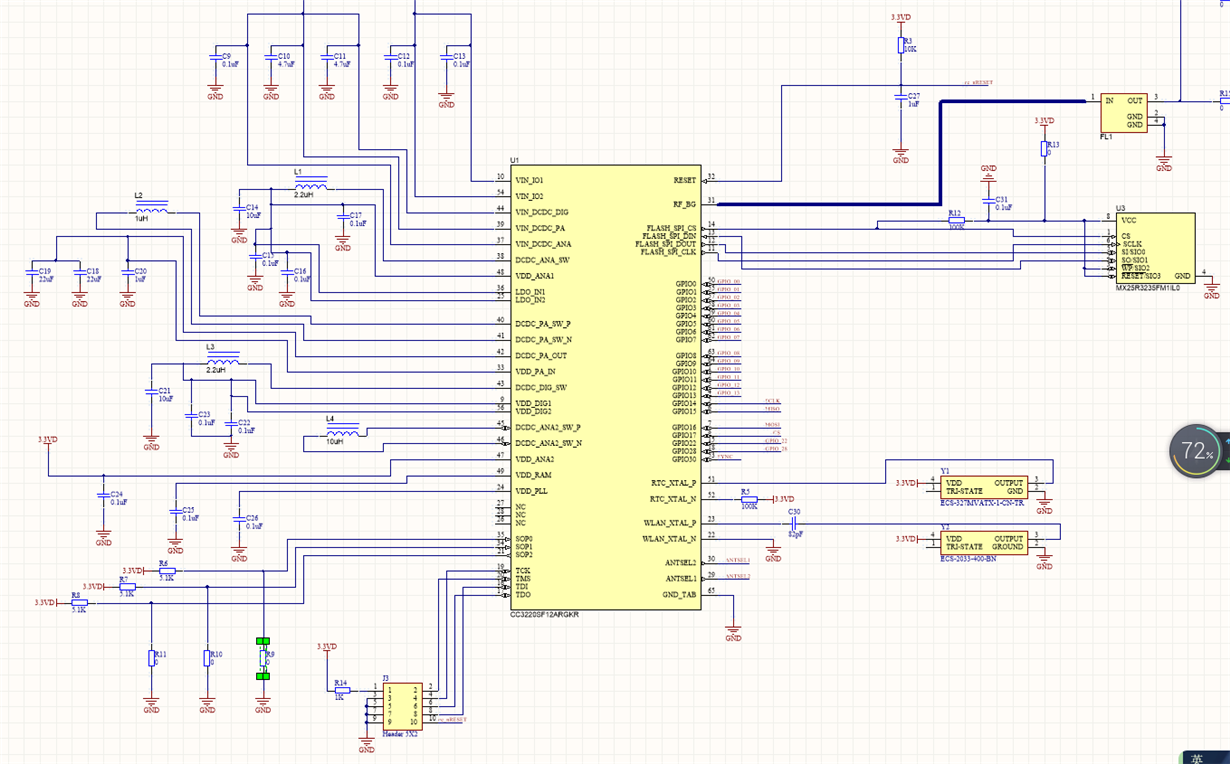
The sop pin is 010 level   , the TDI, TDO, TMS and TCK pins of SDX110 are connected to my board. The following is the schematic diagram. Is it the hardware soldering problem or the problem with my schematic design?
  • Hi,

    For hardware review of your board please contact TI according procedure described here. Be aware that during holiday season can be response time from TI longer.

    I am not a TI employee and from this reason I answering question which are interesting for me only (from this reason I am not doing full review of your schematic). But I can provide you a few important notes and comments.

    • How many layers board do you have? Do you use two or more layers board?
    • How looks voltages at pins VDD_DIGx and VDD_ANAx (you should have pin 48 ~1.8V, pin9 ~1.2V)? If voltages are significantly different, it shows wrong design around internal DC-DC.
    • Before your first attempt to JTAG connect you need to program image with development mode into serial flash. This can be done via UART and Uniflash software (RX, TX, RST, GND). Additional information you find at production line guide. Description how to use Uniflash you find here.
    • At your image above it seems you have connected RST, TDI, TDO, TCK, TMS but you not have connected GND. Without proper GND connection JTAG/SWD cannot work properly.

    Jan

  • I use a four-layer board.
    Regarding your third suggestion, I tried to use uniflash and serial port for debugging, but I couldn't connect to my device either. I guess there was a problem with the circuit design or soldering.
    I connected the ground wire to no effect.
    Thanks for your help, thanks

  • I found that the voltage of my 48-pin and 9-pin is wrong, because when drawing the schematic, I did not find how to connect VDD_ANA and VDD_DIG. Do you have any suggestions?

    best wishes.

  • According to the schematic diagram, pins 9 and 48 do not need external power supply, right? If the voltage is wrong, is there a problem with my crystal oscillator?

  • Hi,

    In case you have wrong voltage at internal DC-DC pins it can means:

    btw ... what voltages do you have at VDD_DIGx and VDD_ANAx pins? But in case voltages are not correct CC3220 is not running and Uniflash and JTAG connection is not possible.

    Jan

  • My 48 pin is 0.4V and my 9 pin is 0V.
    And I tested my 32.768K input crystal oscillator test frequency is only 2K, which should affect the internal voltage supply, I am now waiting for the hardware processing.

  • Also, my friend, these two pins are not powered by external input. If my 3.3V chip is ok, this should be the voltage generated inside the chip. Why is my voltage wrong?

  • Hi,

    When CC3220 device is used at wide-voltage mode, required voltages for proper function of CC3220 chip are generated by internal DC-DC.

    I am not sure if this is your case, but it is pretty common design issue with CC32xx device. When PCB layout is not properly done according layout recommendation, internal DC-DC may not be functional. Detail information how DC-DC loops should be designed are stated at link above.

    Jan