This thread has been locked.

If you have a related question, please click the "Ask a related question" button in the top right corner. The newly created question will be automatically linked to this question.

WL1837MOD: Inquiries about Antenna Configuration

Part Number: WL1837MOD
Other Parts Discussed in Thread: AM3356,

Hi team

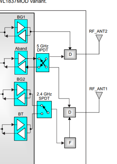
Customer is developing their system with WL1837MOD/AM3356(Linux). Although Customer is verifying WiFI signals with their board, they noticed that the output to RF_ANT1 and RF_ANT2 is reversed. Their antenna's configuration is as follows. I'm not sure what's wrong. Can I have Expert's advice/comments on this, please?

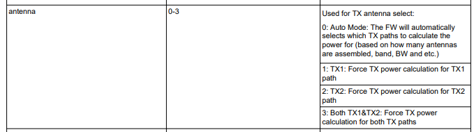
<<< RF_ANT1 configuration >>>

#cd /usr/sbin/wlconf

# ./wlconf -i /lib/firmware/ti-connectivity/wl18xx-conf.bin -o /lib/firmware/ti-connectivity/wl18xx-conf.bin --set wl18xx.phy.spare0=0x08

# calibrator wlan0 plt power_mode on

# calibrator wlan0 wl18xx_plt tune_channel 7 0 1

# calibrator wlan0 wl18xx_plt set_tx_power 20000 0 0 7 0 1 0 1 0 0 0 0

# calibrator wlan0 wl18xx_plt tx_tone_start 1 0 1 0

# calibrator wlan0 wl18xx_plt tx_tone_stop

<<< RF_ANT2 configuration>>>

#cd /usr/sbin/wlconf

# ./wlconf -i /lib/firmware/ti-connectivity/wl18xx-conf.bin -o /lib/firmware/ti-connectivity/wl18xx-conf.bin --set wl18xx.phy.spare0=0x00

calibrator wlan0 plt power_mode on

calibrator wlan0 wl18xx_plt tune_channel 7 0 1

calibrator wlan0 wl18xx_plt set_tx_power 20000 0 0 7 0 2 0 1 0 0 0 0

calibrator wlan0 wl18xx_plt tx_tone_start 1 0 2 0

calibrator wlan0 wl18xx_plt tx_tone_stop

And then, customer was able to see WiFi RF signals on RF_ANT1, however, customer was Not able to see WiFi RF signals on RF_ANT2. Although customer was trying to check their commands, they are not sure this root cause. it will be appreciated if Expert will share example (Ant2, 5GHz Transmit).

Customer is referring https://processors.wiki.ti.com/index.php/WL18xx_TX_Testing#ANT1_.26_ANT2_Assembly_Validation_for_Production

Best regards,

Miyazaki

  • Hi,

    To confirm, customer is seeing WiFi RF signal on ANT1 when ./wlconf -i /lib/firmware/ti-connectivity/wl18xx-conf.bin -o /lib/firmware/ti-connectivity/wl18xx-conf.bin --set wl18xx.phy.spare0=0x08 ?

    and on ANT2 when ./wlconf -i /lib/firmware/ti-connectivity/wl18xx-conf.bin -o /lib/firmware/ti-connectivity/wl18xx-conf.bin --set wl18xx.phy.spare0=0x00 ?

    Regards

    Saurabh

  • Hi Saurabh,

    For 2.4GHz, customer is able to see RF signal on ANT2 when the set wl18xx.phy.spare0=0x08 and set “wl18xx_plt set_tx_power 20000 0 0 7 0 1 0 1 0 0 0 0” . On the contrary, , customer is able to see RF signal on ANT1 when the set wl18xx.phy.spare0=0x00 and set “set_tx_power 20000 0 0 7 0 2 0 1 0 0 0 0” . would you expect this result?

    For 5GHz, customer reported , although customer tried to do some configuration/set commands, they were not able to check 5Hz signal on ANT2 therefore, customer is requesting TI to prepare example-script which includes like above wlconf and calibrator commands.

    Best regards,

    Miyazaki

  • Hi Miyazaki,

    The antennas are backwards when comparing to the RF path - Please review our datasheet, and I've also attached the block diagram for reference.

    It looks like you were able to get RF output on ANT2. Please let us know if you have any other questions.

    BR,

    Vince 

  • Hi Vince,

    Please let me confirm it. When customer execute the following command, TI expects WL18xx output RF signal from RF_ANT1?

     # ./wlconf -i /lib/firmware/ti-connectivity/wl18xx-conf.bin -o /lib/firmware/ti-connectivity/wl18xx-conf.bin --set wl18xx.phy.spare0=0x00

    And then,  when customer set " --set wl18xx.phy.spare0=0x08",  TI expects WL18xx output RF signal from RF_ANT2?

    Best regards,

    Miyazaki

  • Hi Vincent,

    I received additional information about this. regardless of wl18xx.phy.spare0 setting, when customer was executing the following calibrator command, customer was able to confirmed RF-output on ANT2

    # calibrator wlan0 wl18xx_plt set_tx_power 20000 0 0 7 0 1 0 1 0 0 0 0

    And then, when customer was executing the following calibrator command, customer was able to confirmed RF-output on ANT1

    # calibrator wlan0 wl18xx_plt set_tx_power 20000 0 0 7 0 2 0 1 0 0 0 0

    I mean, when customer sets parameter of “set_tx_power Command” to “1”, customer confirmed RF-output on ANT2. when customer sets parameter of “set_tx_power Command” to “2”, customer confirmed RF-output on ANT1. I attached customer’s verification prompt-log(1321.logs.zip).


    According to “Calibrator Tool User's Guide 3.4 Set TX Power (https://www.ti.com/lit/ug/swru562/swru562.pdf)”, antenna parameter is defined as follows.


    I’m not sure if TX1/TX2 is related to ANT1/ANT2. However, when customer set antenna=1 (TX1), customer is able to see RF-output on ANT2. when customer set antenna=2 (TX2), customer is able to see RF-output on ANT1.

    Would you expect this behavior?

    Can we have Expert’s comments on this within today (your time), please? I’m sorry for rushing you but it is really appreciated your quick reply because customer’s RTM is soon…

    Best regards,

    Miyazaki

  • Hi Vincent,

    Since I noticed customer did not execute " load_wlcore.sh" and " sta_start.sh" after " ./wlconf" command, I'm requesting customer to do so.

    Best regards,

    Miyazaki

  • Hi Vince,

    First of all, regarding the antenna parameter of “set_tx_power”, Can we have your Expert’s comments on this, please?

    when customer set antenna=1 (TX1), customer is able to see RF-output on ANT2. when customer set antenna=2 (TX2), customer is able to see RF-output on ANT1. Therefore, I believe that TX1 means BG1(ANT2) and TX2 means BG2(ANT1). If so, that makes sense. Would you clarify it, please? sorry for rushing you..

    Best regards,

    Miyazaki

  • Hi Miyazaki,

    Sorry for the delay. I will look into this first thing tomorrow and get you an answer.

    BR,

    Vince 

  • Hi Vince,

    Can I have any comments on this, please?

    best regards, Miyazaki

  • Hi Miyazaki, sorry for the delay.

    Yes the antenna and RF paths are swapped - please review the block diagram i attached previously. RF (BG and A) Path 1 corrosponds to Ant 2 and RF path 2 is Ant 1.

     BR,

    Vince 

  • Hi Vince,

    Thanks for your clarification.

    I shared your comments with customer. For 2.4GHz, customer said, they were able to understand antenna configuration. the remained inquiry is 5GHz output.

    For 5GHz RF-out, however, when customer set antenna=1 (TX1) on calibrator command, RF signal is outputting on BG2(ANT1). Also, when customer set antenna=2 (TX2) on calibrator command, customer said, they are not able to see RF-signal on both ANT1 and ANT2. I’m asking customer what calibrator command customer tried to do. For 5GHz, would you think that this calibrator command is not able to support RF-output on ANT2 ?

    According to the block diagram which you mentioned, I believe it supports this. can I have your Expert’s advice/comments on this, please?

    If you will be able to share example 5HGz RF-output script. It will be really appreciated.

    Best regards, Miyazaki

  • Hi Vince,

    Can we have your Expert's comments on customer's inquiry, please?

    For 5GHz RF-output, should customer set wl18xx.phy.spare0 by "wlconf" command?

    Best regards,

    Miyazaki

  • Yes, wlconf can be used to configure the 5GHz output.

    BR,

    Vince 

  • Vince,

    I’m requesting customer to try the following wlconf command before executing calibrator. I’d like to wait for their feedback.

    Although I’m reading https://www.ti.com/lit/ug/swru562/swru562.pdf , I noticed there is wl18xx.phy.number_of_assembled_ant5 parameter for wlconf. Would you think customer also should need to set wl18xx.phy.number_of_assembled_ant5 =0x02?

    Best regards,

    Miyazaki

  • If they have two antennas for 5GHz, yes. If not, then it should be set to 0x01.

    BR,

    Vince