This thread has been locked.

If you have a related question, please click the "Ask a related question" button in the top right corner. The newly created question will be automatically linked to this question.

WL1801MOD: Can SMD_CLK be limited to 25MHz?

Part Number: WL1801MOD
Other Parts Discussed in Thread: WL1801, WL1271, WL1837, , WL1837MOD

WL1801 has replaced TiWI-BLE (WL1271) in a design using i.MX6 (ARM) platform.

OS is yocto 3.10

Wilink8 is used. Ti-compat-wireless 3.11.18-r8.a9.22

TiWI-BLE used SMD_CLK of 25MHz while WL1801 run at 50MHz.

I have 0.3% failure rate with WL1801.    The WL1801 fails to be detected.

Can I limit the SMD_CLK to 25MHz with WL1801?  I want to see if the slower clock rate would impact the failure rate.

Setting max-frequency = <25000000>;  in the device tree did not influence it.

  • Hi, 

    Can you please confirm which kernel version is used here? Also please refer to the latest driver integration guide here https://www.ti.com/tool/download/WILINK8-WIFI-NLCP. Also what is the type of failure that you are seeing? Please let us know the details. 

    Regards, 

    Sudharshan K N 

  • Linux-3.10.54-dey+g441c8d4

    Failure mode:  SMD detection process never reaches HI-SPEED mode.

    SMD messages captured are:

    CMD 52 Clear I/O Abort register
    CMD 52   Set RESET bit in I/O Abort register, it will auto clear
    CMD 0
    CMD 8
    CMD 5   IO_SEND_OP_COND
    CMD 5   IO_SEND_OP_COND
    CMD 5   IO_SEND_OP_COND
    CMD 5   IO_SEND_OP_COND
    CMD 55
    CMD 55
    CMD 55
    CMD 55
    CMD 1

    Modules loaded: compat   wlcore_sdio

    Modules failed to load:   cfg80211  mac80211   wlcore   wl18xx
    wlan0 is not present, thus nmcli d wifi fails.

    In all instances, wifi function (nmcli d wifi) works during a pretest of the system.
    It is during subsequent boot cycles that we run into this behavior.

  • SD1 bus during detection… on a unit that FAILS detection,


    Start Dir CMD R/W FUNC# RAW Stuff Reg Stuff WriteData CRC7 End

    0

    1

    110100

    0

    000

    0

    0

    0000 0000 0000 0011 0

    0

    0000 0000

    0011 100

    1

                  52

    0

    1

    110100

    1

    000

    0

    0

    0000 0000 0000 0011 0

    0

    0000 1000

    1001 111

    1

                  52 

    0

    1

    000000

    0

    000

    0

    0

    0000 0000 0000 0000 0

    0

    0000 0000

    1001 010

    1

                    0 

    0

    1

    001000

    0

    000

    0

    0

    0000 0000 0000 0000 0

    0

    1010 1010

    1001 000

    1

                    8 

    0

    1

    000101

    0

    000

    0

    0

    0000 0000 0000 0000 0

    0

    0000 0000

    0101 101

    1

                    5 

    0

    1

    000101

    0

    000

    0

    0

    0000 0000 0000 0000 0

    0

    0000 0000

    0101 101

    1

                    5 

    0

    1

    000101

    0

    000

    0

    0

    0000 0000 0000 0000 0

    0

    0000 0000

    0101 101

    1

                    5 

    0

    1

    000101

    0

    000

    0

    0

    0000 0000 0000 0000 0

    0

    0000 0000

    0101 101

    1

                    5 

    0

    1

    110111

    0

    000

    0

    0

    0000 0000 0000 0000 0

    0

    0000 0000

    0110 010

    1

                 55 

    0

    1

    110111

    0

    000

    0

    0

    0000 0000 0000 0000 0

    0

    0000 0000

    0110 010

    1

                 55 

    0

    1

    110111

    0

    000

    0

    0

    0000 0000 0000 0000 0

    0

    0000 0000

    0110 010

    1

                 55 

    0

    1

    110111

    0

    000

    0

    0

    0000 0000 0000 0000 0

    0

    0000 0000

    0110 010

    1

                 55 

    0

    1

    000001

    0

    000

    0

    0

    0000 0000 0000 0000 0

    0

    0000 0000

    1111 100

    1

                   1

  • Hi, 

    WiLink8 R8.8 is the latest driver and has several updates to many of the known issues. This is based on 4.19 version of kernel. Please let us know the options at your end to update to this kernel variant. 

    Regards, 

    Sudharshan K N 

  • Hi, 

    Can you please share the DTS file used? Also please take a look at the below E2E to check if the issue is the same. 

    https://e2e.ti.com/support/wireless-connectivity/wifi/f/968/p/945976/3498909?tisearch=e2e-sitesearch&keymatch=wlink8%2525252525252520SDIO%2525252525252520clock#3498909

    Regards, 

    Sudharshan K N 

  • Hello Sudharshan,

    Moving to kernel 4.19 introduces so many other conflict in the system, it is not desirable to look into for this particular problem.

    I have attached my devicetree...

    /*
     * Copyright 2014 Digi International, Inc.
     * Copyright 2012 Freescale Semiconductor, Inc.
     * Copyright 2011 Linaro Ltd.
     *
     * The code contained herein is licensed under the GNU General Public
     * License. You may obtain a copy of the GNU General Public License
     * Version 2 or later at the following locations:
     *
     * http://www.opensource.org/licenses/gpl-license.html
     * http://www.gnu.org/copyleft/gpl.html
     */
    
    /dts-v1/;
     
    #include "imx6q.dtsi"
    #include <dt-bindings/interrupt-controller/irq.h>
    
    / {
    	model = "Raven Cruizer Pro";
    	compatible = "digi,ccimx6sbc", "digi,ccimx6", "fsl,imx6q";
    	digi,machine,name = "ccimx6sbc";
    
    	aliases {
    		mxcfb0 = &mxcfb1;
    		mxcfb1 = &mxcfb2;
    		mxcfb2 = &mxcfb3;
    //		mxcfb3 = &mxcfb4;
    	};
    
    	memory {
    		reg = <0x10000000 0x40000000>;
    	};
    
    	wlan_en_reg: wlan_en {
    		compatible = "regulator-fixed";
    		regulator-name = "wlan-en";
    		regulator-min-microvolt = <1800000>;
    		regulator-max-microvolt = <1800000>;
    
    		gpio = <&gpio7 6 0>;
    		startup-delay-us = <70000>;
    		enable-active-high;
    	};
    
    	mxcfb1: fb@0 {
    		compatible = "fsl,mxc_sdc_fb";
    		disp_dev = "hdmi";
    		interface_pix_fmt = "RGB24";
    		mode_str ="1920x1080M@60";
    		default_bpp = <32>;
    		int_clk = <0>;
    		late_init = <0>;
    		status = "okay";
    	};
    
    	mxcfb2: fb@1 {
    		compatible = "fsl,mxc_sdc_fb";
    		disp_dev = "ldb";
    		interface_pix_fmt = "RGB24";
    		mode_str ="TFT800480";
    		default_bpp = <32>;
    		int_clk = <1>;
    		late_init = <0>;
    		status = "okay";
    	};
    
    	mxcfb3: fb@2 {
    		compatible = "fsl,mxc_sdc_fb";
    		disp_dev = "lcd";
    		interface_pix_fmt = "RGB24";
    		mode_str ="TFT800480";
    		default_bpp = <32>;
    		int_clk = <1>;
    		late_init = <0>;
    		status = "okay";
    	};
    
    //disable mxcfb4 for now as the ldb config was overriding parts of our LCD config (1/2 share DI 3/4 share)
    	/*mxcfb4: fb@3 {
    		compatible = "fsl,mxc_sdc_fb";
    		disp_dev = "ldb";
    		interface_pix_fmt = "RGB24";
    		mode_str ="TFT800480";
    		default_bpp = <32>;
    		int_clk = <0>;
    		late_init = <0>;
    		status = "okay";
    	};*/
    
    	lcd@0 {
    		compatible = "fsl,lcd";
    		ipu_id = <1>;
    		disp_id = <0>;
    		default_ifmt = "RGB24";
    		pinctrl-names = "default";
    		pinctrl-0 = <&pinctrl_ipu1_1>;
    		display = <&ampire>;
    		status = "okay";
    	};
    
    	ampire: TFT800480@0 {
    		bits-per-pixel = <32>;
    		bus-width = <24>;
    
    		display-timings {
    			timing {
    				clock-frequency = <33260000>;
    				hactive = <800>;
    				vactive = <480>;
    				hfront-porch = <64>;
    				hback-porch = <64>;
    				hsync-len = <128>;
    				vback-porch = <25>;
    				vfront-porch = <10>;
    				vsync-len = <10>;
    				hsync-active = <0>;
    				vsync-active = <0>;
    				de-active = <1>;
    				pixelclk-active = <1>;
    			};
    		};
    	};
    
    
    	backlight {
    		compatible = "pwm-backlight";
    		pwms = <&pwm2 0 5000000>;
    		brightness-levels = <0 4 8 16 32 64 128 255>;
    		default-brightness-level = <7>;
    	};
    
    	radar {
    		compatible = "imx-pwm-freq";
    		pwms = <&pwm1 0 5000000>;
    	};
    
    	wlan {
    		compatible = "ti,wilink8";
    		interrupt-parent = <&gpio7>;
    		interrupts = <7 IRQ_TYPE_LEVEL_HIGH>;
    		clocks = <&refclock>;
    		clock-names = "refclock";
    
    		refclock: refclock {
    			compatible = "ti,wilink-clock";
    			#clock-cells = <0>;
    			clock-frequency = <38400000>;
    		};
    	};
    
    /*Remove code for wl1801
    	kim {
                compatible = "kim";
                nshutdown_gpio = <197>;  // GPIO7_IO5 
                dev_name = "/dev/ttymxc1";
                flow_cntrl = <1>;
                baud_rate = <2000000>;
        };
    
    	btwilink {
    		compatible = "btwilink";
    	};
    */
    };
    
    &audmux {
    //	pinctrl-names = "default";
    //	pinctrl-0 = <&pinctrl_audmux_2>;
    	status = "disabled";
    };
    
    &cpu0 {
    	arm-supply = <&reg_arm>;
    	soc-supply = <&reg_soc>;
    	pu-supply = <&reg_pu>;
    };
    
    &ecspi1 {
    	fsl,spi-num-chipselects = <2>;
    	cs-gpios = <&gpio2 30 0>,<&gpio4 10 0>;
    
    	pinctrl-names = "default";
    	pinctrl-0 = <&pinctrl_ecspi1_3>;
    	status = "okay";
    };
    
    /* 10/100/1000 KSZ9031 PHY */
    &fec {
    	pinctrl-names = "default";
    	pinctrl-0 = <&pinctrl_enet_4>;
    	phy-mode = "rgmii";
    	phy-reset-gpios = <&gpio1 25 2>;
    	phy-reset-duration = <10>;
    	phy-reset-wait = <1>;
    //	phy-supply = <&ldo4>;
    	status = "okay";
    };
    
    &gpc {
    	fsl,cpu_pupscr_sw2iso = <0xf>;
    	fsl,cpu_pupscr_sw = <0xf>;
    	fsl,cpu_pdnscr_iso2sw = <0x1>;
    	fsl,cpu_pdnscr_iso = <0x1>;
    	fsl,ldo-bypass = <0>; /* No ldo-bypass */
    	fsl,wdog-reset = <1>; /* watchdog select of reset source */
    	pu-supply = <&reg_pu>;
    };
    
    &gpu {
    	pu-supply = <&reg_pu>;
    };
    
    &hdmi_audio {
    	status = "disabled";
    };
    
    &hdmi_cec {
    	pinctrl-names = "default";
    	pinctrl-0 = <&pinctrl_hdmi_cec_2>;
    	status = "disabled";
    };
    
    &hdmi_core {
    	ipu_id = <1>;
    	disp_id = <1>;
    	status = "disabled";
    };
    
    &hdmi_video {
    	fsl,phy_reg_vlev = <0x0294>;
    	fsl,phy_reg_cksymtx = <0x800d>;
    	status = "disabled";
    };
    
    &ldb {
        clock_less_38mhz = <1>;
        ipu_id = <0>;
        disp_id = <0>;
        ext_ref = <1>;
        mode = "sep0";
        sec_ipu_id = <0>;
        sec_disp_id = <1>;
        status = "okay";
        display = <&ampire>;
        sec_display = <&ampire>;
    };
    
    &i2c1 {
    	clock-frequency = <100000>;
    	pinctrl-names = "default";
    	pinctrl-0 = <&pinctrl_i2c1_2>;
    	status = "okay";
    
    	st1633: touchscreen@55 {
    		compatible = "sitronix";
    		reg = <0x55>;
    		interrupt-parent = <&gpio7>;
    		interrupts = <13 0x2>; //(gpio 205)
    		gpios = <&gpio4 5 0>; //GPIO_19__GPIO4_IO05, RESET pin (gpio 101)
    		status = "okay";
    	};
    
    	exc3132: touchscreen@04 {
    		compatible = "eeti,egalax_ts";
    		reg = <0x04>; 
    		interrupt-parent = <&gpio7>;
    		interrupts = <13 0x2>; //(gpio 205)
    		wakeup-gpios = <&gpio7 13 0>;
    		#gpios = <&gpio4 5 0>; //GPIO_19__GPIO4_IO05, RESET pin (gpio 101)
    		status = "okay";
    	};
    
    };
    
    &i2c2 {
    	clock-frequency = <100000>;
    	pinctrl-names = "default";
    	pinctrl-0 = <&pinctrl_i2c2_3>;
    	status = "okay";
    
    /*	pmic:pfuze200@08 {
    		compatible = "fsl,pfuze200";
    		reg = <0x08>;
    		interrupt-parent=<&gpio3>;
    		interrupts=<28 0x2>;
    		status = "okay";
    	};
    */
    	pmic:pf0200@08 {
    		compatible = "fsl,pf0200";
    		reg = <0x08>;
    		interrupt-parent=<&gpio3>;
    		interrupts=<28 0x2>;
    		interrupt-controller;
    		#interrupt-cells = <1>;
    		staus = "okay";
    
    		onkey {
    			compatible = "fsl,pf0200-onkey";
    			interrupts = <0>;
    			interrupt-names = "ONKEYI";
    			interrupt-parent = <&pmic>;
    			fsl,key-power;
    		};
    /*		regulators {
    			compatible = "fsl,pf0200-regulator";
    			sw1a_reg: sw1ab {
    				regulator-min-microvolt = <300000>;
    				regulator-max-microvolt = <1875000>;
    				regulator-boot-on;
    				regulator-always-on;
    				regulator-ramp-delay = <6250>;
    			};
    
    			sw2_reg: sw2 {
    				regulator-min-microvolt = <400000>;
    				regulator-max-microvolt = <3300000>;
    				regulator-boot-on;
    				regulator-always-on;
    			};
    
    			sw3a_reg: sw3a {
    				regulator-min-microvolt = <400000>;
    				regulator-max-microvolt = <3300000>;
    				regulator-boot-on;
    				regulator-always-on;
    			};
    
    			sw3b_reg: sw3b {
    				regulator-min-microvolt = <400000>;
    				regulator-max-microvolt = <3300000>;
    				regulator-boot-on;
    				regulator-always-on;
    			};
    
    			swbst_reg: swbst {
    				regulator-min-microvolt = <5000000>;
    				regulator-max-microvolt = <5150000>;
    			};
    
    			snvs_reg: vsnvs {
    				regulator-min-microvolt = <1000000>;
    				regulator-max-microvolt = <3000000>;
    				regulator-boot-on;
    				regulator-always-on;
    			};
    
    			vref_reg: vrefddr {
    				regulator-boot-on;
    				regulator-always-on;
    			};
    
    			vgen1_reg: vgen1 {
    				regulator-min-microvolt = <800000>;
    				regulator-max-microvolt = <1550000>;
    			};
    
    			vgen2_reg: vgen2 {
    				regulator-min-microvolt = <800000>;
    				regulator-max-microvolt = <1550000>;
    			};
    
    			vgen3_reg: vgen3 {
    				regulator-min-microvolt = <1800000>;
    				regulator-max-microvolt = <3300000>;
    			};
    
    			vgen4_reg: vgen4 {
    				regulator-min-microvolt = <1800000>;
    				regulator-max-microvolt = <3300000>;
    				regulator-always-on;
    			};
    
    			vgen5_reg: vgen5 {
    				regulator-min-microvolt = <1800000>;
    				regulator-max-microvolt = <3300000>;
    				regulator-always-on;
    			};
    
    			vgen6_reg: vgen6 {
    				regulator-min-microvolt = <1800000>;
    				regulator-max-microvolt = <3300000>;
    				regulator-always-on;
    			};
    		};
    */	};
    };
    
    &i2c3 {
    	clock-frequency = <100000>;
    	pinctrl-names = "default";
    	pinctrl-0 = <&pinctrl_i2c3_5>;
    	status = "okay";
    
    	pca9552: pca955x@60 {
    		compatible = "pca9552";
    		reg = <0x60>;
    	};
    };
    
    &iomuxc {
    	pinctrl-names = "default";
    	pinctrl-0 = <&pinctrl_hog_1>;
    
    	usbotg {
    		pinctrl_usbotg_4: usbotggrp-4 {
    			fsl,pins = <
    				MX6QDL_PAD_ENET_RX_ER__USB_OTG_ID 0x17059
    //				MX6QDL_PAD_EIM_D22__USB_OTG_PWR 0x17059 moved because it was backfeeding power
    //				MX6QDL_PAD_KEY_COL4__USB_OTG_OC 0x17059 EIMD21
    			>;
    		};
    	};
    
    	i2c2 {
    		pinctrl_i2c2_3: i2c2grp-3 {
    			fsl,pins = <
    				MX6QDL_PAD_KEY_COL3__I2C2_SCL 0x4001b8b1
    				MX6QDL_PAD_KEY_ROW3__I2C2_SDA 0x4001b8b1
    				MX6QDL_PAD_EIM_D28__GPIO3_IO28 0x80000000
    			>;
    		};
    	};
    
    	i2c3 {
    		pinctrl_i2c3_5: i2c3grp-5 {
    			fsl,pins = <
    				MX6QDL_PAD_GPIO_5__I2C3_SCL  0x4001b8b1
    				MX6QDL_PAD_GPIO_6__I2C3_SDA  0x4001b8b1
    			>;
    		};
    	};
    
    	uart1 {
    		pinctrl_uart1_4: uart1grp-4 {//CPRO
    			fsl,pins = <
    				MX6QDL_PAD_CSI0_DAT10__UART1_TX_DATA 0x1b0b1
    				MX6QDL_PAD_CSI0_DAT11__UART1_RX_DATA 0x1b0b1
    				MX6QDL_PAD_EIM_D19__UART1_CTS_B 0x1b0b1
    				MX6QDL_PAD_EIM_D20__UART1_RTS_B 0x1b0b1
    			>;
    		};
    	};
    
    	uart2 {
    /*		pinctrl_uart2_3: uart2grp-3 {
    			fsl,pins = <
    				MX6QDL_PAD_SD3_DAT4__UART2_RX_DATA   0x1b0b1
    				MX6QDL_PAD_SD3_DAT5__UART2_TX_DATA   0x1b0b1
    				MX6QDL_PAD_SD3_CMD__UART2_CTS_B      0x1b0b1
    				MX6QDL_PAD_SD3_CLK__UART2_RTS_B       0x1b0b1
    			>;
    		};
    */
    
    		pinctrl_uart2_4: uart2grp-4 {
    			fsl,pins = <
    				MX6QDL_PAD_SD3_DAT4__UART2_RX_DATA   0x1b0b1
    				MX6QDL_PAD_SD3_DAT5__UART2_TX_DATA   0x1b0b1
    				MX6QDL_PAD_SD3_CMD__UART2_CTS_B      0x1b0b1
    				MX6QDL_PAD_SD3_CLK__UART2_RTS_B      0x1b0b1
    			>;
    		};
    	};
    
    	uart5 {
    		pinctrl_uart5_3: uart5grp-3 {
    			fsl,pins = <
    				MX6QDL_PAD_KEY_ROW1__UART5_RX_DATA 0x1b0b1
    				MX6QDL_PAD_KEY_COL1__UART5_TX_DATA 0x1b0b1
    			>;
    		};
    	};
    
    	pwm1 {
    		pinctrl_pwm1_1: pwm1grp-1 {
    			fsl,pins = <
    				MX6QDL_PAD_GPIO_9__PWM1_OUT 0x1b0b1
    			>;
    		};
    	};
    
    //LCD backlight out
    	pwm2 {
    		pinctrl_pwm2_1: pwm2grp-1 {
    			fsl,pins = <
    				MX6QDL_PAD_GPIO_1__PWM2_OUT 0x1b0b1
    			>;
    		};
    	};
    
    	flexcan2 {
    		pinctrl_flexcan2_3: flexcan2grp-3 {
    			fsl,pins = <
    				MX6QDL_PAD_KEY_COL4__FLEXCAN2_TX 0x1b0b0
    				MX6QDL_PAD_KEY_ROW4__FLEXCAN2_RX 0x1b0b0
    			>;
    		};
    	};
    
    //0x130b0 -- slow 40ohm 100k pull down hys
    //0x1b0b0 -- slow 40ohm 100k pull up hys
    
    	hog {
    		pinctrl_hog_1: hoggrp-1 {
    			fsl,pins = <
    				MX6QDL_PAD_EIM_DA0__GPIO3_IO00 0x80000000		//HWID_0
    				MX6QDL_PAD_EIM_DA1__GPIO3_IO01 0x80000000		//HWID_1
    				MX6QDL_PAD_EIM_DA2__GPIO3_IO02 0x80000000		//HWID_2
    				MX6QDL_PAD_EIM_DA3__GPIO3_IO03 0x80000000		//HWID_3
    				MX6QDL_PAD_EIM_OE__GPIO2_IO25  0x80000000		//LDID_0
    				MX6QDL_PAD_EIM_RW__GPIO2_IO26 0x80000000		//LDID_1
    				MX6QDL_PAD_EIM_BCLK__GPIO6_IO31 0x80000000		//LDID_2
    				MX6QDL_PAD_EIM_D26__GPIO3_IO26 0x80000000		//LDID_3
    
    				MX6QDL_PAD_SD3_DAT1__GPIO7_IO05 0x1b0b0		//bluetooth Reset
    
    				MX6QDL_PAD_CSI0_DAT4__GPIO5_IO22 0x1b0b1		//LCD reset
    //				MX6QDL_PAD_GPIO_9__PWM1_OUT 0x1b0b1			//RADAR OUT, 
    
    //				MX6QDL_PAD_GPIO_18__GPIO7_IO13 0x80000000		//TOUCH_INT
    //				MX6QDL_PAD_GPIO_19__GPIO4_IO05 0x1b0b1			//TOUCH_RST
    
    				MX6QDL_PAD_EIM_D16__GPIO3_IO16 0x1b0b1			//12V_SW_INT
    				MX6QDL_PAD_EIM_D17__GPIO3_IO17 0x1b0b1			//GPS_SW_INT
    
    				MX6QDL_PAD_NANDF_CLE__GPIO6_IO07 0x1b0b1		//12V_SW_EN
    				MX6QDL_PAD_NANDF_CS0__GPIO6_IO11 0x1b8b1		//12V_OUT_FAULT_RST
    				MX6QDL_PAD_NANDF_CS1__GPIO6_IO14 0x1b0b1		//12V_OUT_SEn
    				MX6QDL_PAD_NANDF_WP_B__GPIO6_IO09 0x1b0b1		//GPS_SW_EN
    				MX6QDL_PAD_NANDF_CS2__GPIO6_IO15 0x1b8b1		//GPS_OUT_FAULT_RST
    				MX6QDL_PAD_NANDF_CS3__GPIO6_IO16 0x1b0b1		//GPS_OUT_SEn
    
    				MX6QDL_PAD_EIM_D18__GPIO3_IO18	0x1b0b1			//PWR_INT
    /*
    
    				MX6QDL_PAD_GPIO_4__GPIO1_IO04   0x80000000
    				MX6QDL_PAD_NANDF_D0__GPIO2_IO00 0x80000000
    				MX6QDL_PAD_NANDF_D2__GPIO2_IO02 0x80000000
    				MX6QDL_PAD_NANDF_D3__GPIO2_IO03 0x80000000
    				MX6QDL_PAD_NANDF_ALE__GPIO6_IO08 0x80000000
    				MX6QDL_PAD_GPIO_16__GPIO7_IO11	 0x80000000
    				MX6QDL_PAD_GPIO_0__CCM_CLKO1    0x130b0
    				MX6QDL_PAD_NANDF_CS2__GPIO6_IO15 0x80000000
    				MX6QDL_PAD_NANDF_CS3__GPIO6_IO16 0x80000000
    				MX6QDL_PAD_EIM_CS1__GPIO2_IO24 0x80000000
    				MX6QDL_PAD_EIM_A25__GPIO5_IO02 0x80000000
    	//			MX6QDL_PAD_EIM_D23__GPIO3_IO23 0x80000000 //not used
    				MX6QDL_PAD_NANDF_CS0__GPIO6_IO11 0x80000000
    				MX6QDL_PAD_NANDF_CS1__GPIO6_IO14 0x80000000
    				MX6QDL_PAD_EIM_EB3__GPIO2_IO31 0x80000000
    				MX6QDL_PAD_SD3_RST__GPIO7_IO08  0x1b0b1		//proc run led
    				MX6QDL_PAD_NANDF_D5__GPIO2_IO05 0x80000000   //MSATA_LOADED
    				MX6QDL_PAD_GPIO_4__GPIO1_IO04 0x80000000	//MCA_IRQ_N
    				MX6QDL_PAD_NANDF_D1__GPIO2_IO01 0x1b0b0 //AUDIO_AMP_ENABLE
    				MX6QDL_PAD_EIM_DA8__GPIO3_IO08 0x1b0b0  //GPS_RESET_N
    				MX6QDL_PAD_EIM_DA9__GPIO3_IO09 0x1b0b0 //CP2108_RESET_N
    				MX6QDL_PAD_EIM_DA10__GPIO3_IO10 0x1b0b0 //USB_HUB_RESET_N
    				MX6QDL_PAD_SD3_DAT2__GPIO7_IO06 0x1b0b0 //mipi-csi reset
    //				MX6QDL_PAD_SD3_DAT3__GPIO7_IO07 0x80000000 //wlan irq
    				MX6QDL_PAD_EIM_D22__GPIO3_IO22 0x130b0
    				MX6QDL_PAD_CSI0_DATA_EN__GPIO5_IO20 0x1b0b0 //mcp251x reset_N
    //		
    */		
    			>;
    		};
    	};
    };
    
    /*
    &mipi_csi {
    	status = "okay";
    	ipu_id = <0>;
    	csi_id = <0>;
    	v_channel = <0>;
    	lanes = <1>;
    };
    
    
    &mipi_dsi {
    	dev_id = <0>;
    	disp_id = <0>;
    	lcd_panel = "TRULY-WVGA";
    	resets = <&mipi_dsi_reset>;
    	status = "okay";
    };
    */
    
    &pcie {
    	//pwr-gpios = <&gpio3 19 0>;
    	rst-gpios = <&gpio7 12 0>;
    	status = "disabled";
    };
    
    &pwm1 {
    	pinctrl-names = "default";
    	pinctrl-0 = <&pinctrl_pwm1_1>;
    	status = "okay";
    };
    
    
    &pwm2 {
    	pinctrl-names = "default";
    	pinctrl-0 = <&pinctrl_pwm2_1>;
    	status = "okay";
    };
    
    
    &ssi2 {
    	fsl,mode = "i2s-slave";
    	status = "okay";
    };
    
    &uart1 {
    	pinctrl-names = "default";
    	pinctrl-0 = <&pinctrl_uart1_4>;
    	fsl,uart-has-rtscts;
    	//digi,pwr-en-gpio = <&gpio2 26 0>;
    	status = "okay";
    };
    
    &uart2 {
    	pinctrl-names = "default";
    	pinctrl-0 = <&pinctrl_uart2_4>;
    	fsl,uart-has-rtscts;
    	status = "okay";
    };
    
    &uart3 {
    	pinctrl-names = "default";
    	pinctrl-0 = <&pinctrl_uart3_2>;
    	fsl,uart-has-rtscts;
    	//digi,pwr-en-gpio = <&gpio2 26 0>;
    	status = "okay";
    };
    
    &uart4 {
    	pinctrl-names = "default";
    	pinctrl-0 = <&pinctrl_uart4_1>;
    	status = "okay";
    };
    
    &uart5 {
    	pinctrl-names = "default";
    	pinctrl-0 = <&pinctrl_uart5_3>;
    	status = "okay";
    };
    
    &usbh1 {
    	fsl,reset-gpio = <&gpio3 10 0>;
    	status = "okay";
    };
    
    &usbotg {
    	pinctrl-names = "default";
    	pinctrl-0 = <&pinctrl_usbotg_4>;
    	fsl,power-line-polarity-active-high;
    	fsl,over-current-polarity-active-low;
    	status = "okay";
    };
    
    
    &usdhc1 {
    	pinctrl-names = "default", "state_100mhz", "state_200mhz";
    	pinctrl-0 = <&pinctrl_usdhc1_1>;
    	pinctrl-1 = <&pinctrl_usdhc1_1_100mhz>;
    	pinctrl-2 = <&pinctrl_usdhc1_1_200mhz>;
    //	pinctrl-names = "default", "sleep";
    //	pinctrl-0 = <&mmc3_pins_default &wlan_pins_default>;
    //	pinctrl-1 = <&mmc3_pins_sleep &wlan_pins_sleep>;
    	vmmc-supply = <&wlan_en_reg>;
      	bus-width = <4>;
    //	non-removable;
    	ti,non-removable;
    	ti,needs-special-hs-handling;
        cap-power-off-card;
    	keep-power-in-suspend;
    	status = "okay";
    	#address-cells = <1>;
    	#size-cells = <0>;
    
    
        wlcore {
               compatible = "wlcore";
               gpio = <31>;
               platform-quirks = <1>;
               board-ref-clock = <2>;
        };
    
    	wlcore: wlcore@0 {
    //	wlcore: wlcore@2 {
    		compatible = "ti,wl1801";
    		reg = <2>;
    		interrupt-parent = <&gpio7>;
    //		interrupts = <17 IRQ_TYPE_EDGE_RISING>; 
    		interrupts = <7 0x04>; //IRQ_TYPE_LEVEL_HIGH
    	};
    /*
        wlcore {
               compatible = "wlcore";
               gpio = <31>;
               platform-quirks = <1>;
               board-ref-clock = <2>;
        };
    
    	#address-cells = <1>;
    	#size-cells = <0>;
    	wlcore: wlcore@2 {
    		compatible = "ti,wl1271";
    		reg = <2>;
    		interrupt-parent = <&gpio7>;
    		interrupts = <7 0x04>; //IRQ_TYPE_LEVEL_HIGH
    		ref-clock-frequency = <38400000>;
    	};
    */


    };
    
    &usdhc2 {
    	pinctrl-names = "default", "state_100mhz", "state_200mhz";
    	pinctrl-0 = <&pinctrl_usdhc2_2>;
    	pinctrl-1 = <&pinctrl_usdhc2_2_100mhz>;
    	pinctrl-2 = <&pinctrl_usdhc2_2_200mhz>;
    	no-1-8-v;
    	bus-width = <4>;
    	non-removable;
    	status = "okay";
    };
    
    &usdhc4 {
    	pinctrl-names = "default", "state_100mhz", "state_200mhz";
    	pinctrl-0 = <&pinctrl_usdhc4_1>;
    	pinctrl-1 = <&pinctrl_usdhc4_1_100mhz>;
    	pinctrl-2 = <&pinctrl_usdhc4_1_200mhz>;
    	bus-width = <8>;
    	non-removable;
    	no-1-8-v;
    	status = "okay";
    };
    
    &flexcan1 {
    	pinctrl-names = "default";
    	pinctrl-0 = <&pinctrl_flexcan1_1>;
    //	stby-gpios = <&gpio1 2 0>;
    	status = "okay";
    };
    
    &flexcan2 {
    	pinctrl-names = "default";
    	pinctrl-0 = <&pinctrl_flexcan2_3>;
    //	stby-gpios = <&gpio1 5 0>;
    	status = "okay";
    };
    
    &sata {
    	status = "disabled";
    };
    
    &vpu {
    	pu-supply = <&reg_pu>;
    };
    

  • Sudharshan,

    I will try the "broken-mmc1-highspeed" from your device tree reference.

    Thanks,

    Dave

  • Hi Dave, 

    Thanks for the update!! Will wait to see how this goes. 

    Regards, 

    Sudharshan K N 

  • Adding   "broken-mmc-highspeed;"   and   "max-frequency = <25000000>;"   to my device tree did not bring the SMD_CLK down from 50MHz.
    I assume   "broken-mmc-highspeed"   is a component of wilink8 version 8.8  or  of kernel version 4.19. 

  • Hi, 

    Does the issue happen only with certain devices or does the issue happens with every device at different point in time? Above failure rate is mentioned as 0.3%. Does this apply to all device or only for a certain devices? Please confirm. 

    Regards, 

    Sudharshan K N 

  • .3% failure rate of wifi function at our factory test since we moved to WL1801.
    The factory test simply calls   nmcli d wifi,    and the resulting scan and signal strengths determine pass/fail.
    There are 2 failure modes we have seen...

    1.   The i.mx6 will not identify wl1801 during the low clock phase of SD1 port.
    2.   The wl1801 is identified, drivers are loaded, but the wifi scan returns empty, and repeatedly returns empty.
                 Sometimes, this behavior is resolved after one or more power cycles.

    I did succeed in setting SMD_CLK to 25MHz.  
    It made no impact on my wifi problem.

    I am using wl18xx-fw                            version ol_r8.a9.14
    I am using ti-compat-wireless-wl18xx  version ol_r8.a9.22

  • Hi, 

    Thanks for the details!

    Have you checked the power up sequence? Does the device power up properly and has primary clock and RTC clock available? 

    Also for #2 failure, does it consistently fail or does some of the devices recover after power cycling? Please let me know. 

    Is it possible to lower the clock frequency further to 2MHz just for test? 

    Regards, 

    Sudharshan K N 

  • Hi, 

    Also in the DTS file for the interrupt settings our setups are configured with IRQ_TYPE_EDGE_RISING. Would it be possible to make this change and retest? 

    	wlcore: wlcore@0 {
    //	wlcore: wlcore@2 {
    		compatible = "ti,wl1801";
    		reg = <2>;
    		interrupt-parent = <&gpio7>;
    //		interrupts = <17 IRQ_TYPE_EDGE_RISING>; 
    		interrupts = <7 0x04>; //IRQ_TYPE_LEVEL_HIGH
    	};

    Regards, 

    Sudharshan K N 

  • Hi,

    I looked into the power up seq and didn't see a problem, but I will look again.

    The #2 failure has been restored on only 2 devices (so far), but that was after many power cycles, as well as much time powered down and set aside. 

    I tried setting the SMD_CLK to 2MHz and 12.5MHz, but they defaulted to 25MHz.
    It seems 25<Hz and 50MHz may be the only options for operational mode.

    Thanks,

    Dave

  • I changed the interrupt setting.
    I did not see any impact on my test subjects.

  • Hi, 

    I found few additional resources mentioned here regarding the iMX6 integration https://community.nxp.com/t5/i-MX-Processors/Step-by-step-How-to-setup-TI-Wilink-WL18xx-with-iMX6-Linux-3-10/m-p/452922. Let me know if this provides additional information. Also since the issue is sporadic on only a few boards the issue might be in HW power up sequence or in the interface. Would it be possible to share the schematics (part of it related to WL8) with us to take a look at it? 

    Regards, 

    Sudharshan K N 

  • Hi,

    I have attached the wifi portion of the schematic.
    It was designed around WL1837, but went into production with WL1801.

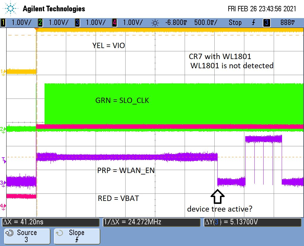
    I have also attached a scope shot of startup of a unit that will no longer recognize WL1801.
    The one concern is WLAN_EN rises to 1V until probably the devicetree is read.

    I have added an external pull down resistor here, but have not seen any change in behavior.
    However the datasheet mentioned damage could be done to the part if an invalid power up sequence is used.
    So I am not ruling this out as being the root cause.

    Thoughts?

    eMMC_BT_WIFI.pdf

  • Hi, 

    Thanks for sharing!! Do you have the waveform capture from a goof unit? Please refer to the data sheet (https://www.ti.com/lit/ds/symlink/wl1801mod.pdf?ts=1614634205854&ref_url=https%253A%252F%252Fwww.ti.com%252Fproduct%252FWL1801MODfor the power up sequence. We need to have RTC clock enabled before VBAT and VIO for normal operation. Also need to have the WL_EN ON after we have the VBAT ON. Please make sure you have the timing correct as shown below. 

    Also WL1837MOD supports dual mode operation. This means the module may have multiple antennas. However WL1801MOD supports only 2.5GHz band and doesn't support BT. So this module will just need a single antenna. Please make sure you have this antenna configuration and also make sure that the configuration file is updated to reflect the same. 

    Regards, 

    Sudharshan K N 

  • Hi,

    Are you positive the clock needs to be present before VBAT rises?

    From the datasheet, VBAT and VIO appear to rise before the clock starts.

  • Hi, 

    Please refer to figure 5.2 for details of the timing needed. Fig 5.4 provides with all signals included including TCXO. In the plots sent earlier, it did not seem like WL_EN is ON before RTC clock is enabled. 

    Regards, 

    Sudharshan K N