


Dear E2E community,
I am glad to be joining this community! I would like to ask for your support.
Currently, we are developing a product at CC3220S that utilize UART2 for establish RS485 communication. To do so, controlling of read/write enable pin is a critical point (RS485 is half-duplex). Therefore, write callback is to be used. As we could learn from API there are two ways:
1)
    uartParams.writeMode = UART2_Mode_CALLBACK;
    uartParams.writeCallback = callbackFxn;
2)
    uartParams.writeMode = UART2_Mode_NONBLOCKING;
    uartParams.writeCallback = NULL;
    uartParams.eventCallback = eventFxn;
    uartParams.eventMask = UART2_EVENT_TX_FINISHED;
Unfortunately, both do not work as intended.
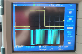
In 1) approach, the callbackFxn is called in completely non-deterministic manner. It is somehow related to TX ring buffer size (set in SysConfg) and transmitted data size. This callback is unpredictable so not very useful in our application. At the bottom I attach some example code. Perhaps, I do something wrong? Below, I attach some screens from oscilloscope (yellow falling edge - start transmission, rising - callbackFxn). In both cases transmitted data size is 46 bytes:
a) TX ring buffer 64 bytes:
b) TX buffer 16 bytes:

2) approach is much more deterministic but eventFxn is always too early. For me, it looks like DMA (which unfortunately cannot be disabled in this MCU) generate interrupt at the beginning of transmitting the last data chunk to the peripheral. Generally, for 115200 this event is called 1,5 ms before end of transmission, see pictures below:

Note that this issue cannot be reproduced with just debugger breakpoint because breakpoint does not halt the DMA.
Could you help me solve this problem? Of course, we could put timeout in the callback but it is workaround in bad style.
1)
void callbackFxn(UART2_Handle handle, void *buffer, size_t count,
        void *userArg, int_fast16_t status)
{
    if (status != UART2_STATUS_SUCCESS) {
        /* RX error occured in UART2_read() */
        while (1);
    }

    GPIO_write(CONFIG_GPIO_LED_0, CONFIG_GPIO_LED_ON);

}

void *mainThread(void *arg0)
{
    char              input;
    const char        writeFrame[] = "0123456789ABCDEFGHIJKLMNOPRSTUWYZ0123456789\r\n";
    UART2_Handle      uart;
    UART2_Params      uartParams;
    uint32_t          status = UART2_STATUS_SUCCESS;

    /* Call driver init functions */
    GPIO_init();

    /* Configure the LED pin */
    GPIO_setConfig(CONFIG_GPIO_LED_0, GPIO_CFG_OUT_STD | GPIO_CFG_OUT_LOW);

    /* Create a UART in CALLBACK read mode */
    UART2_Params_init(&uartParams);
    uartParams.readMode = UART2_Mode_BLOCKING;
    uartParams.readCallback = NULL;
    uartParams.writeMode = UART2_Mode_NONBLOCKING;
    uartParams.writeCallback = callbackFxn;
    uartParams.baudRate = 115200;

    uart = UART2_open(CONFIG_UART2_0, &uartParams);

    if (uart == NULL) {
        /* UART2_open() failed */
        while (1);
    }

    /* Turn on user LED to indicate successful initialization */
    GPIO_write(CONFIG_GPIO_LED_0, CONFIG_GPIO_LED_ON);

    /* Loop forever echoing */
    while (1) {

        /* Wait for any character to start example */
        status = UART2_read(uart, &input, 1, NULL);

        if (status != UART2_STATUS_SUCCESS) {
            /* UART2_read() failed */
            while (1);
        }

        GPIO_write(CONFIG_GPIO_LED_0, CONFIG_GPIO_LED_OFF);

        status = UART2_write(uart, writeFrame, sizeof(writeFrame) - 1, NULL);

        if (status != UART2_STATUS_SUCCESS) {
            /* UART2_write() failed */
            while (1);
        }
    }
}
2)
void eventFxn(UART2_Handle handle, uint32_t event,
              uint32_t data, void *userArg)
{
   if (event != UART2_EVENT_TX_FINISHED) {
       /* RX error occured in UART2_read() */
       while (1);
   }

    GPIO_write(CONFIG_GPIO_LED_0, CONFIG_GPIO_LED_ON);
}

void *mainThread(void *arg0)
{
    char              input;
    const char        writeFrame[] = "0123456789ABCDEFGHIJKLMNOPRSTUWYZ0123456789\r\n";
    UART2_Handle      uart;
    UART2_Params      uartParams;
    uint32_t          status = UART2_STATUS_SUCCESS;

    /* Call driver init functions */
    GPIO_init();

    /* Configure the LED pin */
    GPIO_setConfig(CONFIG_GPIO_LED_0, GPIO_CFG_OUT_STD | GPIO_CFG_OUT_LOW);

    /* Create a UART in CALLBACK read mode */
    UART2_Params_init(&uartParams);
    uartParams.readMode = UART2_Mode_BLOCKING;
    uartParams.readCallback = NULL;
    uartParams.writeMode = UART2_Mode_NONBLOCKING;
    uartParams.writeCallback = NULL;
    uartParams.eventCallback = eventFxn;
    uartParams.eventMask = UART2_EVENT_TX_FINISHED;
    uartParams.baudRate = 115200;

    uart = UART2_open(CONFIG_UART2_0, &uartParams);

    if (uart == NULL) {
        /* UART2_open() failed */
        while (1);
    }

    /* Turn on user LED to indicate successful initialization */
    GPIO_write(CONFIG_GPIO_LED_0, CONFIG_GPIO_LED_ON);

    /* Loop forever echoing */
    while (1) {

        /* Wait for any character to start example */
        status = UART2_read(uart, &input, 1, NULL);

        if (status != UART2_STATUS_SUCCESS) {
            /* UART2_read() failed */
            while (1);
        }

        GPIO_write(CONFIG_GPIO_LED_0, CONFIG_GPIO_LED_OFF);

        status = UART2_write(uart, writeFrame, sizeof(writeFrame) - 1, NULL);

        if (status != UART2_STATUS_SUCCESS) {
            /* UART2_write() failed */
            while (1);
        }
    }
}
PS. It does not matter in this case but in 1) it is possible to send more data than the TX ring buffer size, but in 2) only up to the buffer size.
Edit:
Tested on CC3220S and CC3220SF; SDK 5.10 and 4.40
