This thread has been locked.

If you have a related question, please click the "Ask a related question" button in the top right corner. The newly created question will be automatically linked to this question.

LAUNCHXL-CC1352R1: Communicate to IWR6843 (TIDA-010022 reference)

Part Number: LAUNCHXL-CC3235S
Other Parts Discussed in Thread: TIDA-010022, CC1352R, LAUNCHXL-CC1352R1, IWR6843, MMWAVEICBOOST, CC3235S, SYSCONFIG

1. Please provide me source code of model in the document TIDA-010022 for demo, including device code and demo code on PC GUI via UART.

2. I see description of LAUNCHXL-CC1352R1 has wifi. But when I look at CC1352R MCU, it only has BLE, Multi-standard, Proprietary 2.4 GHz, Sub-1 GHz, Thread, Zigbee. Please confirm whether LAUNCHXL-CC1352R1 really has wifi and can connect via TCP/IP, UDP.

3. Which code in SDK simplelink_cc13x2_26x2 can I refer for CC1352 UART data reading from sensor?

4. Which communication protocol did you use for data transfer between 2 CC1352R1 modules? I think it's TCP/IP.

5. Which sample code can I refer for TCP/IP communication between 2 CC1352R1 modules? I can't find anything about it in SDK.

6. I see the reference design in document TIDA-010022 is sub-1 GHz type. What if I want to modify code for wifi communication? Which part do I need to modify?

I posted this thread in wifi forum even though the design in TIDA-010022 is for sub-1 GHz application because I'm trying to do a project via wifi. If it's more suitable to put this thread in sub-1 GHz 4rum, please help me transfer it to engineers on sub-1 GHz forum if you think this thread is more suitable on that forum. I expect engineers on both wifi & sub-1 GHz 4rum will help me on this issue.

  • Hi Hector,

    1. The source is hosted on the TI Design page, posted here for your reference: 

    The rest of your questions will be answered shortly.

    Regards,

    Justin

  • Hi Justin,

    Thanks. I'll wait for your answer.

    Anyways, the link you sent only has bin files. Do you have source code? I wanna see and modify if needed.

    How about GUI code for target tracking demo?

  • Hector,

    Hector Ta said:
    1. Please provide me source code of model in the document TIDA-010022 for demo, including device code and demo code on PC GUI via UART.

    The TIDA-010022 firmware download includes a set of patches that when applied to the required SDK source files, will give you the entire source code for the project. Please follow the "Building the Firmware" steps in the TIDA-010022 design guide. For receiving the data via UART, there is a TeraTerm macro included in the installer which shows how to parse the data stream from the "collector" LaunchPad. There is no GUI for this design.

    Hector Ta said:
    2. I see description of LAUNCHXL-CC1352R1 has wifi. But when I look at CC1352R MCU, it only has BLE, Multi-standard, Proprietary 2.4 GHz, Sub-1 GHz, Thread, Zigbee. Please confirm whether LAUNCHXL-CC1352R1 really has wifi and can connect via TCP/IP, UDP.

    I believe the statement you are referring to alludes to the fact that the CC1352R1 is part of a SimpleLink device ecosystem which supports multiple protocols.  The CC1352R1 does not itself support Wi-Fi.

    Hector Ta said:
    3. Which code in SDK simplelink_cc13x2_26x2 can I refer for CC1352 UART data reading from sensor?

    The TIDA-10022 user guide has the details on the SDKs used.

    Hector Ta said:
    4. Which communication protocol did you use for data transfer between 2 CC1352R1 modules? I think it's TCP/IP.

    Hector Ta said:
    5. Which sample code can I refer for TCP/IP communication between 2 CC1352R1 modules? I can't find anything about it in SDK.

    It's the 15.4 stack.  Details in the design guide.

    Hector Ta said:
    6. I see the reference design in document TIDA-010022 is sub-1 GHz type. What if I want to modify code for wifi communication? Which part do I need to modify?

    You'll need to start with a suitable example in the Wi-Fi SDK and start from there.  I suggest you start a new thread on this topic.

  • Hi Gus,

    1. Building the Firmware steps in TIDA-010022 only for CC1352c. How about IWR6843 code? The zip file Justin sent to me only has PC_lab_xwr68xx bin file. I need its source code to know how to receive configuration from CC1352 and transfer radar data to CC1352.

    2. do I need to add or remove any resistors on MMWAVEICBOOST to connect it to CC1352 (for both configuration and radar data transfer) via UART ?

    3. I built CC1352 firmware and see in sensor main.c code has many include programs such as nvoctp.h, mmwave_sensor.h... As I understand, I only need to add code from mmwave_sensor.c into main.c to get IWR6843 radar data via UART MSS_LOGGER pin, right? Is MSS_LOGGER pinmux as below?

    4. What's the include program for communication between CC1352 sensor node & collector node ? I guess it's api_mac.c.

  • Hi Justin,

    1. I looked at mmwave_sensor.c code, IWR6843 sends tracking data to CC1352 and stored at pBuf. How about the function to send tracking data from CC1352 sensor node to CC1352 collector?

    2. This package is for sub-1Ghz. What if I want to do BLE application? Which part of code do I need to modify or is still the same?

  • Hector,

    Hector Ta said:
    1. Building the Firmware steps in TIDA-010022 only for CC1352c. How about IWR6843 code? The zip file Justin sent to me only has PC_lab_xwr68xx bin file. I need its source code to know how to receive configuration from CC1352 and transfer radar data to CC1352.

    The bin files for IWR device were taken from the mmWave SDK. Justin can provide more information on the source code for that. For this particular TI design, no changes were needed to be made to the IWR source code. 

    Hector Ta said:
    2. do I need to add or remove any resistors on MMWAVEICBOOST to connect it to CC1352 (for both configuration and radar data transfer) via UART ?

    Yes, the required modifications are given in the design guide for TIDA-010022.

    Hector Ta said:
    3. I built CC1352 firmware and see in sensor main.c code has many include programs such as nvoctp.h, mmwave_sensor.h... As I understand, I only need to add code from mmwave_sensor.c into main.c to get IWR6843 radar data via UART MSS_LOGGER pin, right? Is MSS_LOGGER pinmux as below?

    Hector Ta said:
    4. What's the include program for communication between CC1352 sensor node & collector node ? I guess it's api_mac.c.

    I am sorry, I don't fully understand your question. The patches for the CC1352 firmware detail exactly what changes were made and to which files to get the C1352 to communicate with the IWR device. If you apply the patches, you don't need to make any further changes.

  • Hi Gus,

    1. I'm using CC3235S. I just want to keep the code of IWR6843 and CC1352 that transfer data via UART. Because I think CC1352 & CC3235S are only different in socket programming part, UART code should be the same, right?

    2. I mean in CC1352 sensor node main.c code, I don't see any UART_read() function. So how can CC1352 sensor node get radar data from IWR6843? Then I found out they separate main.c and mmwave_sensor.c code. I think the code in mmwave_sensor.c should be put in main.c. Otherwise, CC1352 will not get radar data.

    3. After I created project (sensor_cc1352r1lp & collector_cc1352r1lp) using patch file for CC1352, I still don't have IWR6843 code. The zip file Justin sent to me only has xwr68xx bin file. Please send me IWR6843 source code for TIDA-010022 design.

  • Hi Hector,

    Hector Ta said:
    1. I'm using CC3235S. I just want to keep the code of IWR6843 and CC1352 that transfer data via UART. Because I think CC1352 & CC3235S are only different in socket programming part, UART code should be the same, right?

    Easiest thing to do would be to reference a CC3235S UART example to understand the UART APIs on that device.  For the CC1352 project, you can see the UART configuration in the mmwave_sensor.c file in the mmwaveTaskInit() function. Specifically you would want to enable two UART ports using same configuration as shown below (I'm taking these code snippets from the patch files).

    +    /* Open mmwave configuration UART port */
    +    UART_Params_init(&mmwaveUartParams);
    +    mmwaveUartParams.writeDataMode = UART_DATA_BINARY;
    +    mmwaveUartParams.readDataMode = UART_DATA_BINARY;
    +    mmwaveUartParams.readReturnMode = UART_RETURN_FULL;
    +    mmwaveUartParams.readEcho = UART_ECHO_OFF;
    +    mmwaveUartParams.baudRate = 115200;  //Configuration baud rate
    +    mmwaveUartParams.readTimeout = 500000 / Clock_tickPeriod;

    ...

    +    /* Open mmwave logger UART port */
    +    UART_Params_init(&mmwaveLoggerUartParams);
    +    mmwaveLoggerUartParams.writeDataMode = UART_DATA_BINARY;
    +    mmwaveLoggerUartParams.readDataMode = UART_DATA_BINARY;
    +    mmwaveLoggerUartParams.readReturnMode = UART_RETURN_FULL;
    +    mmwaveLoggerUartParams.readEcho = UART_ECHO_OFF;
    +    mmwaveLoggerUartParams.baudRate = 921600;  //Configuration baud rate
    +    mmwaveLoggerUartParams.readTimeout = 500000 / Clock_tickPeriod;

    Hector Ta said:
    2. I mean in CC1352 sensor node main.c code, I don't see any UART_read() function. So how can CC1352 sensor node get radar data from IWR6843? Then I found out they separate main.c and mmwave_sensor.c code. I think the code in mmwave_sensor.c should be put in main.c. Otherwise, CC1352 will not get radar data.

    The CC1352 uses RTOS tasks. The UART functions are not in main.c, they are in mmwave_sensor.c.

    Hector Ta said:
    3. After I created project (sensor_cc1352r1lp & collector_cc1352r1lp) using patch file for CC1352, I still don't have IWR6843 code. The zip file Justin sent to me only has xwr68xx bin file. Please send me IWR6843 source code for TIDA-010022 design.

    Note from CC1352 code the IWR is treated as a black box. The CC1352 sends the CommandList to program the IWR as needed. Modification of the IWR is not needed in this case. Do you intend to customize the IWR code?

  • Hi Hector,

    We no longer have the same source used available on TIREX. You can use one of the following:

    1. 3D People Counting
    2. Sense and Direct: HVAC Control
    3. Long Range People Counting

    You shouldn't need to make firmware changes to the CCxxxx device, as it is acting as a passthrough for the mmWave data.

    Regards,

    Justin

  • Hi Gus,

    1. I see in CC3235S_LAUNCHXL.h, there's

    typedef enum CC3235S_LAUNCHXL_UARTName {
        CC3235S_LAUNCHXL_UART0 = 0,
        CC3235S_LAUNCHXL_UART1,
    
        CC3235S_LAUNCHXL_UARTCOUNT
    } CC3235S_LAUNCHXL_UARTName;

    If I use both UART0 and UART1, do I need to set CC3235S_LAUNCHXL_UART1 = 1 ?

    2. Which function code in sensor_cc1352r1lp and collector_cc1352r1lp do the radar data transfer task? e.g. mmwave_sensor.c do UART_read to get data from IWR6843. So which program sends data from CC1352 sensor node to collector node?

    3. Why don't I see #define DEBUG_PRINT and #define MMWAVE_SENSOR in mmwave_sensor.c? Don't we need to use function mmwaveTaskFxn() ? I think we must #define MMWAVE_SENSOR 1, don't we?

    4. Frame header of TLV is 48 bytes. Why UART_read for frame header in readmmwave() only uses 44 bytes? 

    // Read remaining frame header
       len_cnt += UART_read(mmwaveLoggerUartHandle, pBuf, 44);

    Besides, I understand that len_pkt uses pBuf[12] ~ pBuf[15] because sync and version on frame header structure is 8 bytes and 4 bytes, respectively. So why do we declare mmWaveData->frame_number from pBuf[16]? It should be pBuf[19] ~ pBuf[22]. Don't we use platform in frame header structure?

    5. In mmwave_sensor.c, it has some functions UART_control() used UARTCC26XX_CMD_RX_FIFO_FLUSH that was declared in UARTCC26xx.h. But in UARTCC32XX.h, I don't see corresponding variable for FIFO FLUSH. So I declared it by myself

    #define UARTCC32XX_CMD_RX_FIFO_FLUSH            (UART_CMD_RESERVED + 3)

    Is it correct?

    Do we really need to do UART_control() for FIFO flush? What's its correlation to mmWave radar reading?

    6. About IWR6843, I only want to confirm whether its code is same as source code of 3D_people_count or HVAC.

  • Hector Ta said:
    If I use both UART0 and UART1, do I need to set CC3235S_LAUNCHXL_UART1 = 1 ?

    Not sure on this one.  I think you need to start a new thread on this on the Wi-Fi forum.

    Hector Ta said:
    2. Which function code in sensor_cc1352r1lp and collector_cc1352r1lp do the radar data transfer task? e.g. mmwave_sensor.c do UART_read to get data from IWR6843. So which program sends data from CC1352 sensor node to collector node?

    There is a task called mmwaveTaskFxn which takes care of processing the constant data output from the IWR.

    Hector Ta said:
    3. Why don't I see #define DEBUG_PRINT and #define MMWAVE_SENSOR in mmwave_sensor.c? Don't we need to use function mmwaveTaskFxn() ? I think we must #define MMWAVE_SENSOR 1, don't we?

    These are compiler pre-defined symbols. They are added in the CCS project build settings. This is documented in the design guide ("Building The Firmware").

    Hector Ta said:
    4. Frame header of TLV is 48 bytes. Why UART_read for frame header in readmmwave() only uses 44 bytes? 

    Actually, the frame header is 52 bytes (documented in the design guide, "IWR6843 Frame Header").  And the code is not only reading 44 bytes.  If you look at the readmmwave() function it's reading the 52 bytes.

    Hector Ta said:
    5. In mmwave_sensor.c, it has some functions UART_control() used UARTCC26XX_CMD_RX_FIFO_FLUSH that was declared in UARTCC26xx.h. But in UARTCC32XX.h, I don't see corresponding variable for FIFO FLUSH. So I declared it by myself

    Not sure why this is not there on CC32XX.  This should be a new thread on the Wi-Fi forum.

    Hector Ta said:
    6. About IWR6843, I only want to confirm whether its code is same as source code of 3D_people_count or HVAC.

    As Justin mentioned, it is not the same source.

  • Hi Gus,

    1. I think mmwaveTaskFxn is for reading data from mmWave, not transfer data to CC1352 collector via 15.4 stack. I see data from IWR6843 was sent to CC1352 sensor node & stored in pBuf. But I don't see any task to send pBuf to CC1352 collector node.

    2. About UART communication between IWR6843 & CC3235S, I connected Mss_logger pin from IWR6843 EVM to UART1_RX pin on CC3235. I'm testing UART communication with only 1 CC3235. So I didn't send Cfg from PC to CC3235 to IWR6843, but I directly sent Cfg from PC to IWR6843. Then I used Teraterm to check data received on UART1_RX of CC3235S.

    But I don't see any output received on CC3235 when I used Teraterm. I see UART function of CC1352 is similar to CC3235, so mmwave_sensor.c code can be reused. Why didn't I see any output from IWR6843 on CC3235S via UART? I think it's because I set J9 jumper on CC3235S to bottom side to route UART to boosterpack header. So I can't use micro USB port to check received data via COM port using Teraterm. Please suggest me a way to perform both data transfer & check received data at once on CC3235S.

    3. What's the purpose of Util_setEvent() and Ssf_PostAppSem() in mmwave_sensor.c? I think it's to set event then send data to collector via processSensorMsgEvt() in sensor.c program, right? If I use socket in CC3235, do I need to use Util_setEvent & Ssf_PostAppSem or only need to do UART_read(rxBuf) on CC3235 sensor node, then do TCP/IP send(rxBuf)? 

    4. I see in sensor node, semaphorePost() was marked as unused. The document mentioned that we need to use semaphore. Why does this source code does not use it?

    5. In mmWave, we execute task by command Task_create(). So SimpleLink devices execute task by Task_construct() command?

    6. If I don't want to connect CC1352 collector to PC via UART, how can I transfer data between CC1352 sensor node & PC wirelessly? You said protocol is 15.4 stack. So I don't know how to make PC receive data from CC1352 sensor node via 15.4 stack. Is there any other way?

  • Hector Ta said:
    1. I think mmwaveTaskFxn is for reading data from mmWave, not transfer data to CC1352 collector via 15.4 stack. I see data from IWR6843 was sent to CC1352 sensor node & stored in pBuf. But I don't see any task to send pBuf to CC1352 collector node.

    Hector Ta said:
    3. What's the purpose of Util_setEvent() and Ssf_PostAppSem() in mmwave_sensor.c? I think it's to set event then send data to collector via processSensorMsgEvt() in sensor.c program, right? If I use socket in CC3235, do I need to use Util_setEvent & Ssf_PostAppSem or only need to do UART_read(rxBuf) on CC3235 sensor node, then do TCP/IP send(rxBuf)? 

    Hector Ta said:
    4. I see in sensor node, semaphorePost() was marked as unused. The document mentioned that we need to use semaphore. Why does this source code does not use it?

    Ah, you are correct. I misread your previous question. Yes, the mmwaveTaskFxn() continuously runs, parsing the data stream from the IWR looking for the sync word. Once the sync word is found it puts together a packet and sets the SENSOR_MMWAVE_EVT flag using Util_setEvent() and posts the semaphore using Ssf_PostAppSem(). Another task receives that event uses processSensorMsgEvt() to process the data and send it to the collector. pBuf is only a temporary storage buffer used as the data is parsed. The the final data is stored in mmwaveSensor (type Smsgs_mmwaveSensorField_t).

    Hector Ta said:
    6. If I don't want to connect CC1352 collector to PC via UART, how can I transfer data between CC1352 sensor node & PC wirelessly? You said protocol is 15.4 stack. So I don't know how to make PC receive data from CC1352 sensor node via 15.4 stack. Is there any other way?

    Unless your PC has an integrated sub-1GHz radio, this is not possible. I believe there are sub-1GHz USB dongles available, you can ask in the Sub-1GHz forum.

    Regarding your CC3235S questions, these are beyond my knowledge. I would ask you, again, to start a new post on the Wi-Fi forum. I think you need to find a Wi-Fi sensor example and modify that for use with the IWR device. There should be use UART examples for the CC3235S as well. How you architect that code (tasks, semaphores, buffers, etc.) will be based on how that Wi-Fi sensor example code is structured and/or based on your preference. 

  • Hi Gus,

    1. I created a project in CCS based on network_terminal example in SimpleLink CC32xx SDK. Then I added mmwave_sensor.c into the project and invoke mmwaveTaskInit() in network_terminal.c.

    network_terminal project can build normally without mmwaveTaskInit(), but after I added that function into mainThread() of network_terminal.c, it always showed error of unresolved symbol mmwaveSensor and Util_buildUint32

    My purpose is to let CC3235S can transfer Cfg to IWR6843 & receive data from IWR6843 similar to CC1352. I checked UART function of CC1352 is same as CC3235S. That's why I added mmwave_sensor.c in network_terminal project. But this error happened. Please help me handle this issue.

    I couldn't find definition of Util_buildUint32(). Only see it's to Build a uint32_t out of 4 uint8_t variables.

    Not sure why Util_buildUint32() can run on TIDA-010022 with CC1352 but can't run with CC3235S project.

    2. How can I check whether CC3235 received data from IWR6843 successfully if I set J9 jumper to route UART to boosterpack header, not to COM port? I tried to connect/short 3 pins of J9 RX jumper on CC3235S together to see if I can connect to IWR6843 via header & check data by Teraterm via USB port at the same time or not. This time I sent Cfg from PC to IWR6843, not from CC3235. Then I used uartecho example in CC32XX SDK to receive radar data, only use UART_read(uart, rxbuf, BUFSIZE) to get radar data into rxbuf.

    But I see nothing on Teraterm. Please tell me how to check data after received from UART by boosterpack header pins.

  • Hi Gus,

    I've solved compile error of mmwaveSensor and Util_buildUint32.

    But the 2nd problem of data transfer via UART failed is still there. Please help me handle it.

  • Hi Hector,

    I've notified other people in the Wi-Fi team who will be better capable of helping you resolve these issues. You should hear from them shortly.

  • Hi Justin,

    1. Last time you said we can directly send Cfg to IWR6843 from PC, not from CCxxxx. But as I see, in order to receive radar data from MSS_Logger pin, we must set switch S1.1~S1.12 on ICBOOST to use 40-pin header. So I don't think that we can still send Cfg from PC with that settings, but can only send Cfg from CCxxxx. Because with that switch settings, we can only use UART on header pins, not via XDS110 USB port, right? Please double-confirm.

    2. in mmwave_sensor.c code, there's an Cfg array named commandList[] is configuration to send to 6843. If I use demo code in mmwave SDK, do I need to modify commandList[]?If yes, which part?

  • Hi Gus,

    1. I think maybe wifi module still gets data. Which pins in TIDA-010022 are used to send Cfg from CC1352 to 6843, which pin on CC1352 is used to receive data from Mss_logger of MMWAVEICBOOST? In short, how do you connect CC1352R1-Launchpad to IWR6843 MMWAVEICBOOST? As I see, we just align these 2 modules and connect because they match each other, right?

    2. Please tell me the way you check data CC1352 received from IWR6843. Previously, I set jumper to let UART routed to boosterpack header. But I still check data on CCxxxx by connecting its micro USB port to PC and open serial port on Teraterm. Is it a proper way to check data received from MSS_Logger pin of IWR6843 EVM? If not, I need a proper way to check data.

  • Hi Hector,

    1. Yes, stacking the boards from the original TI Design means that the header pins would align.
    2. You have so many posts on this topic that I cannot figure out what you have already tested. Please stick to one thread per topic. In this thread, you said you have an oscilloscope. Are you able to verify that the UART data is being sent by the CC3235?

    Best regards,

    Sarah

  • Hi Sarah,

    I have done initialization for IWR6843 by itself (CLI hard code), in this case it's unnecessary to send Cfg from CC3235 to 6843. But the 2nd method, send Cfg from CC3235 failed to send Cfg to 6843. Even though I have done it, but I want to make both methods can work.

  • Hi Hector,

    Are you able to write to a PC terminal from the CC3235 pin 55 using the UART_write() command?

    Best regards,

    Sarah

  • Hi Sarah,

    Yes, I can. In SysConfig, I used hardware XDS110 (pin 55, 57) for UART0 and I can write command to initialize WLAN, connect to WLAN, send(), recv()... normally. 

    But I can only do it when I only use UART0 at pins 55,57. If I setup UART1 at boosterpack header pins and do UART_control() or UART_write(), UART_read() for UART1, I can't write command to PC terminal (Teraterm) anymore. It seems UART0 being disabled because we can't use pins 55,57 at the same time as boosterpack header pins. Please confirm. If so, how can I enable both UART ports and control them at once? (I think that I need to set UART0 to different header pins. But at this moment, in Sysconfig, Display settings is fixed at "Use hardware" for UART XDS110, so I can't change UART0 to other pins, I can only use p55, 57 for UART0).

  • Part Number: LAUNCHXL-CC3235S

    I set UART0, UART1 pins on Sysconfig as below:

    UART0: use hardware XDS110 (p55, p57), connect to PC via micro USB port.

    UART1: receive only (P45)

    I checked on SysConfig, there's no pin conflict with this settings. And I connected correctly: the pin 45 is located at P4 header (3rd pin from the top). I also checked schematics, P45 can be used directly without having to add or remove any resistor.

    Besides, I shorted 3 pins of J9, J10, respectively, to enable UART for both COM port & boosterpack header. Is it a good way?

    Here's my ti_drivers_config.c code:

    static const UARTCC32XXDMA_HWAttrsV1 uartCC32XXHWAttrs0 = {
        .baseAddr           = UART0_BASE,
        .intNum             = INT_UART0,
        .intPriority        = (~0),
        .flowControl        = UARTCC32XXDMA_FLOWCTRL_NONE,
        .rxChannelIndex     = UDMA_CH8_UARTA0_RX,
        .txChannelIndex     = UDMA_CH9_UARTA0_TX,
        .rxPin              = UARTCC32XXDMA_PIN_57_UART0_RX,
        .txPin              = UARTCC32XXDMA_PIN_55_UART0_TX,
        .ctsPin             = UARTCC32XXDMA_PIN_UNASSIGNED,
        .rtsPin             = UARTCC32XXDMA_PIN_UNASSIGNED,
        .errorFxn           = NULL
      };
    
    const UART_Config UART_config[CONFIG_UART_COUNT] = {
        {   /* CONFIG_UART_0 */
            .fxnTablePtr = &UARTCC32XXDMA_fxnTable,
            .object      = &uartCC32XXObjects0,
            .hwAttrs     = &uartCC32XXHWAttrs0
        },
    };
    
    const uint_least8_t CONFIG_UART_0_CONST = CONFIG_UART_0;
    const uint_least8_t UART_count = CONFIG_UART_COUNT;
    
    static const UART2CC32XX_HWAttrs uart2CC32XXHWAttrs0 = {
        .baseAddr           = UART1_BASE,
        .intNum             = INT_UART1,
        .intPriority        = (~0),
        .flowControl        = UART2CC32XX_FLOWCTRL_NONE,
        .rxDmaChannel       = UDMA_CH10_UARTA1_RX,
        .txDmaChannel       = UART2CC32XX_DMACH_UNASSIGNED,
        .rxPin              = UART2CC32XX_PIN_45_UART1_RX,
        .txPin              = UART2CC32XX_PIN_UNASSIGNED,
        .ctsPin             = UART2CC32XX_PIN_UNASSIGNED,
        .rtsPin             = UART2CC32XX_PIN_UNASSIGNED,
      };
    
    const UART2_Config UART2_config[CONFIG_UART2_COUNT] = {
        {   /* CONFIG_UART2_0 */
            .fxnTablePtr = &UART2CC32XX_fxnTable,
            .object      = &uart2CC32XXObjects0,
            .hwAttrs     = &uart2CC32XXHWAttrs0
        },
    };
    
    const uint_least8_t CONFIG_UART2_0_CONST = CONFIG_UART2_0;
    const uint_least8_t UART2_count = CONFIG_UART2_COUNT;

    Then I initialize both UART ports:

        UART_Handle mmwaveUartHandle;
        UART_Params mmwaveUartParams;
        UART_Handle mmwaveLoggerUartHandle;
        UART_Params mmwaveLoggerUartParams;
    
    /* Open mmwave configuration UART port */
        UART_Params_init(&mmwaveUartParams);
        mmwaveUartParams.writeDataMode = UART_DATA_BINARY;
        mmwaveUartParams.readDataMode = UART_DATA_BINARY;
        mmwaveUartParams.readReturnMode = UART_RETURN_FULL;
        mmwaveUartParams.readEcho = UART_ECHO_OFF;
        mmwaveUartParams.baudRate = 115200;  //Configuration baud rate
        mmwaveUartParams.readTimeout = 500000 / Clock_tickPeriod;
    
        //mmwaveUartHandle = UART_open(Board_UART0, &mmwaveUartParams);
        mmwaveUartHandle = UART_open(CONFIG_UART_0, &mmwaveUartParams);
        if (mmwaveUartHandle == NULL) {
            /* UART_open() failed */
            while (1);
        }
    
    /* Open mmwave logger UART port */
        UART_Params_init(&mmwaveLoggerUartParams);
        mmwaveLoggerUartParams.writeDataMode = UART_DATA_BINARY;
        mmwaveLoggerUartParams.readDataMode = UART_DATA_BINARY;
        mmwaveLoggerUartParams.readReturnMode = UART_RETURN_FULL;
        mmwaveLoggerUartParams.readEcho = UART_ECHO_OFF;
        mmwaveLoggerUartParams.baudRate = 921600;  //Configuration baud rate
        mmwaveLoggerUartParams.readTimeout = 500000 / Clock_tickPeriod;
    
        //mmwaveLoggerUartHandle = UART_open(Board_UART1, &mmwaveLoggerUartParams);
        mmwaveLoggerUartHandle = UART_open(CONFIG_UART2_0, &mmwaveLoggerUartParams);
    
        if (mmwaveLoggerUartHandle == NULL) {
            /* UART_open() failed */
            while (1);
        }

    The purpose of UART0 is to connect to PC and check wifi status via teraterm.

    UART1 is used to get data from mmWave sensor IWR6843.

    When I only use UART0, I can type commands on Teraterm normally. But after added code of UART1 initialization & control, UART0 didn't work as before. I can't type any command on Teraterm.

    Then, I had to remove code of UART0 and only use UART1 code now. But I'm still concerned whether UART1 works normally without UART0.

    Here're my questions:

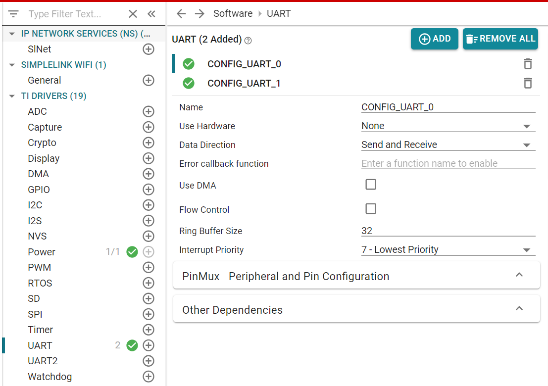
    1. How to make UART0, UART1 work simultaneously with my pins settings as above?

    2. If I can't use both UART ports at once, can I still use UART1 normally after removed UART0 initialization & control?

  • Hi Hector,

    The "UART2" APIs are a different driver module than the UART APIs. You either need to configure both uart0 and uart1 as the UART driver type, or you need to open mmwaveLoggerUartHandle with UART2_open() and use only UART2_ functions with that handle.

    Best regards,

    Sarah

  • Hi Sarah,

    Please confirm whether I understand your meaning correctly:

    1. If I only need to use boosterpack header to communicate to another device, I can change UART0 from "hardware use XDS110" settings to header pins such as P62, P45. So don't need to care about UART1 anymore, right? I tried it, but the issue is: I used a USB-to-UART converter to connect P62,P45,GND,Vcc to converter, then connect to PC. But I can't send command to CC3235 via Teraterm anymore. It seems like CC3235 can only get command when I set UART0 at P55, P75 (use hardware XDS110 settings). And I don't see any data received from sensor via UART_read(). So I don't know whether CC3235 get data well.

    2. You said I can't use 2 UART at once because I set UART_handle instead of UART2_handle. Besides, UART2_params has error.

    I checked UART2.h, it doesn't have readDatamode, writeDatamode as UART1.h. 

    Here's the code I modified for both UART0 and UART1

    UART_Handle mmwaveUartHandle;
    UART_Params mmwaveUartParams;
    UART2_Handle mmwaveLoggerUartHandle;
    UART2_Params mmwaveLoggerUartParams;
    
    void mmwaveTaskInit(void)
    {  
        UART_init();
    
        /* Open mmwave configuration UART port */
        UART_Params_init(&mmwaveUartParams);
        mmwaveUartParams.writeDataMode = UART_DATA_BINARY;
        mmwaveUartParams.readDataMode = UART_DATA_BINARY;
        mmwaveUartParams.readReturnMode = UART_RETURN_FULL;
        mmwaveUartParams.readEcho = UART_ECHO_OFF;
        mmwaveUartParams.baudRate = 115200;  //Configuration baud rate
        mmwaveUartParams.readTimeout = 500000 / Clock_tickPeriod;
    
        mmwaveUartHandle = UART_open(Board_UART0, &mmwaveUartParams);
    
        if (mmwaveUartHandle == NULL) {
            /* UART_open() failed */
            while (1);
        }
    
        /* Open mmwave logger UART port */
        UART_Params_init(&mmwaveLoggerUartParams);
        mmwaveLoggerUartParams.writeMode = UART_DATA_BINARY;
        mmwaveLoggerUartParams.readMode = UART_DATA_BINARY;
        mmwaveLoggerUartParams.readReturnMode = UART_RETURN_FULL;
        mmwaveLoggerUartParams.baudRate = 921600;  //Configuration baud rate
    
        mmwaveLoggerUartHandle = UART2_open(Board_UART1, &mmwaveLoggerUartParams);
    
        if (mmwaveLoggerUartHandle == NULL) {
            /* UART2_open() failed */
            while (1);
        }
    }

    I got some errors of UART2_params. Is there any code to initialize UART2?

  • Hi Hector,

    1. Pin 62 only has one header on the LaunchPad that is populated. Make sure you are using the pin 62 header that does not have a star (*) next to it.

    2. You need to choose a single driver module, either UART or UART2. These are completely separate sets of APIs that can be used for the same peripherals. Consider this as UART code version 1 and UART code version 2.

    You can initialize two UART peripherals, but you should intialize them on the same driver module. If you add two instances to the UART module in SysConfig, they will default to CONFIG_UART_0 and CONFIG_UART_1.

    Best regards,

    Sarah

  • Hi Sarah,

    I see in TIDA-010022 mentioned we can use mmwave_collector_macro.ttl to parse output data of collector node. But I couldn't find that file after installed the firmware folder of TIDA-010022. Please send me that file. Besides, how can I parse target position data (point cloud) from collector node on GUI?

  • Hi Hector,

    Since that file is specific to the TI design, I am not aware of it. Can you ask that question on one of your threads on the radar forum?

    Best regards,

    Sarah