This thread has been locked.

If you have a related question, please click the "Ask a related question" button in the top right corner. The newly created question will be automatically linked to this question.

LAUNCHXL-CC3235S: UART Data port and UART CLI port on IWR6843-ISK MMWAVEICBOOST and CC3235S (TIDA-010022 reference )

Part Number: LAUNCHXL-CC3235S
Other Parts Discussed in Thread: MMWAVEICBOOST, IWR6843, CC3235S, SYSCONFIG, TIDA-010022

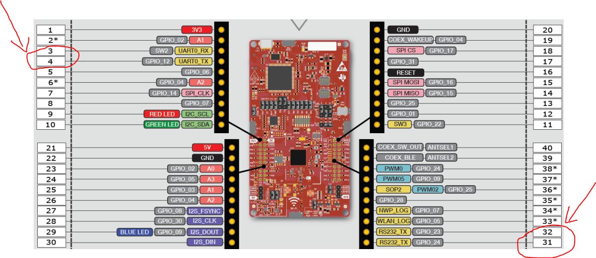
1. In document TIDA-010022 from TI, it mentions 2 UART ports (Data port and CLI port). As I see, MMWAVEICBOOST only uses XDS110 USB port for UART data transfer/image flashing and CC3235 only has UART RX/TX pins on 20-pin header connector. So, which is UART data port and UART CLI port on each module?

2. Previously, I only send configuration to IWR6843 via UART (XDS110 USB port on MMWAVEICBOOST). Why do I need to send Cfg from wifi module according to this document? The Cfg is in PC, so I don't know how CC3235 can send Cfg to IWR6843.

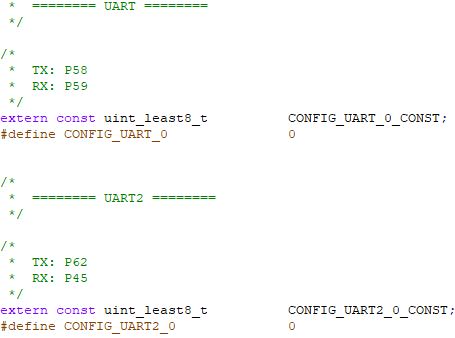
Please show me the position of 2 UART ports as in the photo and how to send Cfg from CC3235 to IWR6843 (why can't I send from PC?)

  • Hi Hector,

    1. The mmWave utilizes one Tx/Rx pair for configuration, and another Tx for data output. Both of these are routed to the XDS110 by default, you can use switch settings so route these to the GPIO pins. From the EVM user's guide, the MSS_LOGGER is the Data Tx out, and the RS232 Rx and Tx are for CLI/configuration.
    2. Device requires Cfg to know how to run. Typically, visualizer sends it from pc, but now you are connected on wifi/sub-1g, so you still need to send device configuration, but it has to come over wifi now. CLI is just a UART interface, so their is no reason why the CC1352 can't do that.

    Regards,

    Justin

  • Hi Justin,

    1. I checked datasheet of 2 modules

    IWR6843 is attached on MMWAVEICBOOST. J5 connector has 2 pins: pin 5 is RS232 (TX from xWR device), pin 7 is RS232 (RX from xWR device). As you mentioned, these 2 pins are for Cfg transfer, right?

    CC3235S: schematics shows there're 2 couples of UART pins as photo below (pin 3,4,31,32). But when I used SysConfig for pin settings, UART pins were assigned on different pin numbers. You can see my pin settings on SysConfig here: TX pin is P62, RX pin is P45. So I guess this pin number is not fixed and we must connect based on pin settings on SysConfig, right?

    So, according to CC3235S pin settings in SysConfig, I must connect like this

    MMWAVEICBOOST       CC3235S

    pin 5 on J5                        P45

    pin 7 on J5                        P62

    GND (pin 4 on J5)            GND (pin 20 or 22 )

    Am I right?

    But above is only UART pins for configuration. Should I connect MSS_logger pin on MMWAVEICBOOST to which pin on CC3235? Do I need to initialize 2 UART ports on CC3235? As I understand, UART0_TX on CC3235 (pin P58) connects to MSS_logger on MMWAVEICBOOST for radar data output, and CLI/Cfg connects as I write above. 

    2. The model in TIDA-010022 is CC1352 collector connects to PC via UART. Does it mean we get Cfg from PC to CC1352 collector, then transfer Cfg to CC1352 sensor node and send to IWR6843?

    3. Do I need to configure mux for MMWAVEICBOOST & CC3235 UART communication as below?

  • Hi Hector,

    1. Your RS232 pin connection looks correct. You should configure a separate UART Rx on the CCxxxx board to recieve the data from the MSS_LOGGER UART pin.

    2. I believe that was the intention of the design. However, the shortcut is to have the IWR6843 configure itself at boot time, then you just collect data and send it back.

    3. Ensure your settings match column 3 of Table 1. in the EVM user's guide.

    Regards,

    Justin

  • Hi Justin,

    1. So SysConfig do pins settings including UART and UART2 as the photo I attached above (UART1 and UART0 in CC3235 datasheet, respectively). Do u confirm that UART2 (TX pin P62, RX pin P45) is for RS232? So I understand that you mean separate UART RX on CC3235 is UART Rx pin P59 for reading data from Mss_logger output pin, right? How about UART RX pin on MMWAVEICBOOST in case I want to read data from external device?

    2. Can I either choose UART1 for RS232 or UART0 for RS232? is it fixed to UART0?

    3. You mentioned the shortcut way to send Cfg to IWR6843 first. In that case we don't need to connect MMWAVEICBOOST to CC3235 via RS232 pins, right? Because those 2 pins are only for configuration transfer.

    4. I see TIDA-010022 mentioned Cfg parameters lowpower 0 0 and pointCloudEn 0. Please tell me 2 things:

    4.1 How to send Cfg from PC to CC3235 collector to IWR6843?

    4.2. I need full Cfg parameters file to directly send to IWR6943 at boot time.

  • Hi Hector,

    I can't answer questions related to CC3235 in this thread, I believe you have another thread open with that team.

    1 and 2: From the IWR6843 standpoint, these are UART, so you can configure them to do whatever you want, as long as you connect Tx to Rx. So you want to send a command to the IWR6843:

    1. Command is in memory, you have a pointer to it <uint8_t * command;>, and you have a command length in bytes <uint32_t com_len;>
      1. command is terminated by "\r\n" so that the cli module will accept it. (It's literally a whole line from the Cfg file)
    2. Assuming you have an api similar to the mmwave uart api, you would call uart_write(<pointer to data>, <data length>)
      1. This becomes uart_write(command, com_len)

    3. If you have the IWR6843 configure itself, it would automatically configure at start up. Then you don't have to worry about CLI. You only need MSS_LOGGER.

    4. This is really just a data transmission. The device is already set up for CLI/UART communication, so the easiest route to configure it is to have the CC3235 send the configuration to the IWR6843 with UART. So the CC3235 needs the configuration. Well you can use the wifi/whatever connectivity to send the cfg from one CC3235 to another. It looks like this:

    PC -> CC3235 -> CC3235 -> IWR6843

    Regards,

    Justin

  • Hi Justin,

    1. I see table of pin configuration for IWR6843 EVM is MSS_UARTB_TX (also known as MSS_LOGGER, right?) can be configured at any ball pin: F14, H14, K13, N13, N5, P10, P7.

    But the position for wiring MSS_LOGGER pin is still fixed at Pin 9 on J6 connector of mmWaveICBoost no matter which ball pin configuration we choose above, right?

    2. You sent zip file of TIDA-010022 firmware to me in another thread (https://e2e.ti.com/support/wireless-connectivity/wifi/f/968/t/910142). But that file does not include source code of IWR6843 to read configuration from wifi module and send tracking data to wifi module. Can you send me full source code of TIDA-010022 in that thread or this thread? Because I don't see you reply in that thread yesterday. Currently, I built CC1352R1 project on CCS by patch files, but only have xwr68xx bin file in TIDA-010022 zip file. I want to see source code and modify it.

    3. Is there any difference between UART API of CC1352 & CC3235? Can I use UART code in TIDA-010022 design for data transfer between IWR6843 & CC3235 sensor node, CC3235 collector & PC? If there's some difference about UART of CC1352 & CC3235, which part is different?

  • Hi Hector,

    1. Yes.
    2. answered here: https://e2e.ti.com/support/wireless-connectivity/wifi/f/968/p/910142/3368851#3368851
    3. This is a question for the wifi forum.

    Regards,

    Justin

  • Hi Justin,

    I used oscilloscope to check signal on both Mss_logger pin and pin 45 (UART1_RX on CC3235). Mss_logger voltage is always at high level (about 33~35V). It means radar hasn't been initialized (hasn't received Cfg settings) successfully. Please tell me how to solve it. I asked a TI member before, but he's a newcomer so he seems to has less experience than you. You are a senior engineer in TI, so I hope you can help me handle this issue. Here's the code I used to send Cfg from CC3235S to IWR6843 and to receive data from Mss_logger pin. After that, I put mmwaveTaskInit(); in main_tirtos.c of CC3235S project. And the result is 6843 uninitialized as mentioned above.

    Note: I set switch S1.1~S1.12 to enable 40-pin connector on MMWAVEICBOOST, and I flashed demo code for IWR6843.

    //#define DEBUG_PRINT
    #define MMWAVE_SENSOR 1
    
    #define MMWAVE_TASK_STACK_SIZE     1024
    #define MMWAVE_TASK_PRIORITY       1
    
    #define MMWAVE_COMMAND_DELAY    1000000     //  1 seconds
    #define MMWAVE_START_DELAY      20000000    //  20 seconds
    
    Task_Struct mmwaveTask;
    Char mmwaveTaskStack[MMWAVE_TASK_STACK_SIZE];
    
    Semaphore_Handle mmwaveSemHandle;
    Semaphore_Struct mmwaveSemStruct;
    
    UART_Handle mmwaveUartHandle;
    UART_Params mmwaveUartParams;
    UART_Handle mmwaveLoggerUartHandle;
    UART_Params mmwaveLoggerUartParams;
    
    uint8_t currentInterval = 0;
    volatile uint8_t sensor_connected = 0;
    
    Smsgs_mmwaveSensorField_t latestMmwaveData;
    
    
    // Updated command list for IWR6843 (60Hz)
    const char *CommandList[] = {"dfeDataOutputMode 1\r",
                        "channelCfg 15 5 0\r",
                        "adcCfg 2 1\r",
                        "adcbufCfg 0 1 1 1\r",
                        "profileCfg 0 60.6 30 10 62 0 0 53 1 128 2500 0 0 30\r",
                        "chirpCfg 0 0 0 0 0 0 0 1\r",
                        "chirpCfg 1 1 0 0 0 0 0 4\r",
                        "frameCfg 0 1 128 0 50 1 0\r",
                        "lowPower 0 1\r",
                        "guiMonitor 1 1 0 0\r",
                        "cfarCfg 6 4 4 4 4 16 16 4 4 50 62 0\r",
                        "doaCfg 600 1875 30 1 1 0\r",
                        "SceneryParam -6 6 0.5 6\r",
                        "GatingParam 4 3 2 0\r",
                        "StateParam 10 5 100 100 5\r",
                        "AllocationParam 250 250 0.25 10 1 2\r",
                        "AccelerationParam 1 1 1\r",
                        "PointCloudEn 0\r",
                        "trackingCfg 1 2 250 20 52 82 50 90\r",
                        "sensorStart\r"
    };
    
    void mmwaveTaskInit(void)
    {
        /* Construct Semaphore */
        Semaphore_Params semParams;
        Semaphore_Params_init(&semParams);
        Semaphore_construct(&mmwaveSemStruct, 0, &semParams);
        mmwaveSemHandle = Semaphore_handle(&mmwaveSemStruct);
    
        /* Configure display task. */
        Task_Params taskParams;
        Task_Params_init(&taskParams);
        taskParams.stack = mmwaveTaskStack;
        taskParams.stackSize = MMWAVE_TASK_STACK_SIZE;
        taskParams.priority = MMWAVE_TASK_PRIORITY;
        Task_construct(&mmwaveTask, mmwaveTaskFxn, &taskParams, NULL);
    
        UART_init();
    
        /* Open mmwave configuration UART port */
        UART_Params_init(&mmwaveUartParams);
        mmwaveUartParams.writeDataMode = UART_DATA_BINARY;
        mmwaveUartParams.readDataMode = UART_DATA_BINARY;
        mmwaveUartParams.readReturnMode = UART_RETURN_FULL;
        mmwaveUartParams.readEcho = UART_ECHO_OFF;
        mmwaveUartParams.baudRate = 115200;  //Configuration baud rate
        mmwaveUartParams.readTimeout = 500000 / Clock_tickPeriod;
    
        mmwaveUartHandle = UART_open(CONFIG_UART_0, &mmwaveUartParams);
        if (mmwaveUartHandle == NULL) {
            /* UART_open() failed */
            while (1);
        }
    
        /* Open mmwave logger UART port */
        UART_Params_init(&mmwaveLoggerUartParams);
        mmwaveLoggerUartParams.writeDataMode = UART_DATA_BINARY;
        mmwaveLoggerUartParams.readDataMode = UART_DATA_BINARY;
        mmwaveLoggerUartParams.readReturnMode = UART_RETURN_FULL;
        mmwaveLoggerUartParams.readEcho = UART_ECHO_OFF;
        mmwaveLoggerUartParams.baudRate = 921600;  //Configuration baud rate
        mmwaveLoggerUartParams.readTimeout = 500000 / Clock_tickPeriod;
      
        mmwaveLoggerUartHandle = UART_open(CONFIG_UART2_0, &mmwaveLoggerUartParams);
    
        if (mmwaveLoggerUartHandle == NULL) {
            /* UART_open() failed */
            while (1);
        }
    }
    
    void mmWave_init(void)
    {
        int command_index;
        int byte_index;
        int retries;
        char input[4];
        char dump;
        int CommandLength;
    
        //UART_control(mmwaveUartHandle, UARTCC32XX_CMD_RX_FIFO_FLUSH, 0);
    
        //parse all the commands in the config files
        for (command_index = 0; command_index<sizeof(CommandList)/sizeof(CommandList[0]); command_index++)
        {
    
    #if 0
            // Send command to mmwave
            UART_write(mmwaveUartHandle, CommandList[command_index], strlen(CommandList[command_index]));
    
            // Wait before sending next command
            Task_sleep(MMWAVE_COMMAND_DELAY / Clock_tickPeriod);
    
    #else
            //parse each command for 5 times if it parses the wrong command.
            //successful write UART: dfeDataOutputMode 1\r
            //successful read UART: dfeDataOutputMode 1\r\nDone\r\n
    
            for (retries=0; retries<5; retries++)
            {
                CommandLength = strlen(CommandList[command_index]);
                for (byte_index=0; byte_index<CommandLength; byte_index++)
                {
                    //each command is parsed a byte per time
                    //read a byte per time and store into array called "dump"
                    UART_write(mmwaveUartHandle, &CommandList[command_index][byte_index], 1);
                    UART_read(mmwaveUartHandle, &dump, 1);
                }
                //take care of additional byte "\n"
                UART_read(mmwaveUartHandle, &dump, 1);
    
                //read next 4 bytes and store it into array called "input"
                UART_read(mmwaveUartHandle, input, 4);
    
                //keep reading until reaches the last byte ">"
                while (dump!= '>')
                {
                    UART_read(mmwaveUartHandle, &dump, 1);
                }
    
                //if array "input" is equal to "Done", which means it receives the right command
                if (input[0]=='D' && input[1]=='o' && input[2]=='n' && input[3]== 'e')
                {
                    break;
                }
            }
    #endif
        }
    }
    
    /*!
     * @brief       Main task function
     *
     * @param       a0 -
     * @param       a1 -
     */
    #define EMPTY_TEST
    
    Void mmwaveTaskFxn(UArg a0, UArg a1)
    {
        // Wait for the mmWave to power on before initializing the mmWave
        Task_sleep(MMWAVE_START_DELAY / Clock_tickPeriod);
    
        // Wait for the sensor to be connected to the collector
        while(!sensor_connected);
    
        // Initialize and start the mmWave
        mmWave_init();
    
        //UART_control(mmwaveLoggerUartHandle, UARTCC32XX_CMD_RX_FIFO_FLUSH, 0);
    
    #ifdef MMWAVE_SENSOR
        while(1)
        {
            /* Get mmWave value */
            uint8_t status = readmmwave(&mmwaveSensor);
    
            switch(status)
            {
                case MMWAVE_STATUS_SUCCESS:
                    #ifdef DEBUG_PRINT
                    UART_write(mmwaveLoggerUartHandle, "S", 1);
                    #endif
                    //Util_setEvent(&Sensor_events, SENSOR_MMWAVE_EVT);
                    //Ssf_PostAppSem();
                    break;
                case MMWAVE_STATUS_INVALID_SYNC:
                    #ifdef DEBUG_PRINT
                    UART_write(mmwaveLoggerUartHandle, "!SYNC\n\r", 7);
                    #endif
                    break;
                case MMWAVE_STATUS_TLV_TOO_LONG:
                    #ifdef DEBUG_PRINT
                    UART_write(mmwaveLoggerUartHandle, "TLV>PKT\n\r", 9);
                    #endif
                    break;
                case MMWAVE_STATUS_PKT_TOO_LONG:
                    #ifdef DEBUG_PRINT
                    UART_write(mmwaveLoggerUartHandle, "PKT!=CNT\n\r", 10);
                    #endif
                    break;
                case MMWAVE_STATUS_INVALID_TLV:
                    #ifdef DEBUG_PRINT
                    UART_write(mmwaveLoggerUartHandle, "!TLV\n\r", 6);
                    #endif
                    break;
            }
    
        }
    #endif
    }
    
    Smsgs_mmwaveSensorField_t mmwaveSensor =
        { 0 };
    
    uint8_t readmmwave(Smsgs_mmwaveSensorField_t* mmWaveData)
    {
        mmWaveDataUART_t mmWaveUart;
        char input = 0x0;
        char pBuf[250];
        uint32_t i = 0;
        uint32_t count = 0;
        uint32_t len_cnt = 0;
        uint32_t len_pkt = 0;
    
        uint32_t num_tlv = 0;
        uint32_t tlv_index = 0;
        uint32_t tlv_type = 0;
        uint32_t tlv_length = 0;
    
        uint32_t obj_index = 0;
        uint32_t num_obj = 0;
    
        // SYNC WORD: 02 01 04 03 06 05 08 07
        // Wait for start of sync word
        while(input != 0x02)
        {
            UART_read(mmwaveLoggerUartHandle, &input, 1);
        }
    
        // Verify that next 7 bytes are the correct sync pattern
        len_cnt = 1;
        count = 0;
        while(count < 7)
        {
            len_cnt += UART_read(mmwaveLoggerUartHandle, &input, 1);
            switch(count)
            {
                case 0: if(input == 0x01) count++; else return MMWAVE_STATUS_INVALID_SYNC; break;
                case 1: if(input == 0x04) count++; else return MMWAVE_STATUS_INVALID_SYNC; break;
                case 2: if(input == 0x03) count++; else return MMWAVE_STATUS_INVALID_SYNC; break;
                case 3: if(input == 0x06) count++; else return MMWAVE_STATUS_INVALID_SYNC; break;
                case 4: if(input == 0x05) count++; else return MMWAVE_STATUS_INVALID_SYNC; break;
                case 5: if(input == 0x08) count++; else return MMWAVE_STATUS_INVALID_SYNC; break;
                case 6: if(input == 0x07) count++; else return MMWAVE_STATUS_INVALID_SYNC; break;
            }
        }
    
        #ifdef DEBUG_PRINT
        UART_write(mmwaveLoggerUartHandle, "$", 1);
        #endif
    
        // Read remaining frame header
        len_cnt += UART_read(mmwaveLoggerUartHandle, pBuf, 44);
        len_pkt = ((uint32_t)((pBuf[12]) & 0x00FF) +
                  ((uint32_t)((pBuf[13]) & 0x00FF) << 8) +
                  ((uint32_t)((pBuf[14]) & 0x00FF) << 16) +
                  ((uint32_t)((pBuf[15]) & 0x00FF) << 24));
    
        mmWaveData->frame_number = ((uint32_t)((pBuf[16]) & 0x00FF) +
                ((uint32_t)((pBuf[17]) & 0x00FF) << 8) +
                ((uint32_t)((pBuf[18]) & 0x00FF) << 16) +
                ((uint32_t)((pBuf[19]) & 0x00FF) << 24));
    
        num_tlv = (pBuf[40] & 0x00FF) + ((pBuf[41] & 0x00FF) << 8);
    
    
        // Process each TLV structure
        for(tlv_index=0; tlv_index<num_tlv; tlv_index++)
        {
            // Read TLV header
            len_cnt += UART_read(mmwaveLoggerUartHandle, pBuf, 8);
    
            // TLV type
            tlv_type =  ((uint32_t)((pBuf[0]) & 0x00FF) +
                        ((uint32_t)((pBuf[1]) & 0x00FF) << 8) +
                        ((uint32_t)((pBuf[2]) & 0x00FF) << 16) +
                        ((uint32_t)((pBuf[3]) & 0x00FF) << 24));
    
            // TLV length
            tlv_length =((uint32_t)((pBuf[4]) & 0x00FF) +
                        ((uint32_t)((pBuf[5]) & 0x00FF) << 8) +
                        ((uint32_t)((pBuf[6]) & 0x00FF) << 16) +
                        ((uint32_t)((pBuf[7]) & 0x00FF) << 24));
    
            if(tlv_length > len_pkt){
                return MMWAVE_STATUS_TLV_TOO_LONG;
            }
    
            switch(tlv_type)
            {
                case 0x07:
    
                    // Save length for offline processing. Do not want to slow down
                    // reading the UART stream by calculating the number of objects
                    tlv_length = tlv_length - 8;
                    num_obj = tlv_length;
                    obj_index = 0;
    
                    while(tlv_length > 0)
                    {
                        //Board_Led_toggle(board_led_type_LED1);
    
                        // Save first 10 object information
                        if(obj_index < SMSGS_SENSOR_MMWAVE_MAX_OBJ)
                        {
                            // Save object information (tid, posx, posy)
                            len_cnt += UART_read(mmwaveLoggerUartHandle, mmWaveUart.objInfo[obj_index].info, 12);
                            // Discard unneeded information
                            len_cnt += UART_read(mmwaveLoggerUartHandle, pBuf, 56);
                        }
                        else
                        {
                            // Already read max number of objects. Read the remaining objects and discard
                            len_cnt += UART_read(mmwaveLoggerUartHandle, pBuf, 68);
                        }
                        // Increase number of objects saved
                        obj_index++;
                        // Decrement length counter to see if there are any additional data to be processed
                        tlv_length = tlv_length - 68;
                    }
    
                    #ifdef DEBUG_PRINT
                    UART_write(mmwaveLoggerUartHandle, "&", 1);
                    #endif
    
                    break;
    
                case 0x06:
                    tlv_length = tlv_length - 8;
                    while(tlv_length > 0){
                        len_cnt += UART_read(mmwaveLoggerUartHandle, pBuf, 16);
                        tlv_length = tlv_length - 16;
                    }
    
                    #ifdef DEBUG_PRINT
                    UART_write(mmwaveLoggerUartHandle, "^", 1);
                    #endif
                    break;
                case 0x08:
                    tlv_length = tlv_length - 8;
                    len_cnt += UART_read(mmwaveLoggerUartHandle, pBuf, tlv_length);
                    #ifdef DEBUG_PRINT
                    UART_write(mmwaveLoggerUartHandle, "*", 1);
                    #endif
                    break;
                default:
                    return MMWAVE_STATUS_INVALID_TLV;
            }
        }
    
    
        // POST PROCESSING
    
        // Only continue processing if full frame was received
        if(len_cnt != len_pkt)
            return MMWAVE_STATUS_PKT_TOO_LONG;
    
        // Number of objects
        mmWaveData->num_objs = num_obj / 68;
        // Object information
        for(i=0; i<SMSGS_SENSOR_MMWAVE_MAX_OBJ; i++)
        {
            // Only calculate if there's valid data in the array
            if(i < mmWaveData->num_objs)
            {
                mmWaveData->objInfo[i].tid  = Util_buildUint32(mmWaveUart.objInfo[i].info[0],
                                                               mmWaveUart.objInfo[i].info[1],
                                                               mmWaveUart.objInfo[i].info[2],
                                                               mmWaveUart.objInfo[i].info[3]);
                mmWaveData->objInfo[i].posx = Util_buildUint32(mmWaveUart.objInfo[i].info[4],
                                                               mmWaveUart.objInfo[i].info[5],
                                                               mmWaveUart.objInfo[i].info[6],
                                                               mmWaveUart.objInfo[i].info[7]);
                mmWaveData->objInfo[i].posy = Util_buildUint32(mmWaveUart.objInfo[i].info[8],
                                                               mmWaveUart.objInfo[i].info[9],
                                                               mmWaveUart.objInfo[i].info[10],
                                                               mmWaveUart.objInfo[i].info[11]);
            }
            else
            {
                mmWaveData->objInfo[i].tid  = 0;
                mmWaveData->objInfo[i].posx = 0;
                mmWaveData->objInfo[i].posy = 0;
            }
        }
    
    
        //UART_control(mmwaveLoggerUartHandle, UARTCC32XX_CMD_RX_FIFO_FLUSH, 0);
    
        return MMWAVE_STATUS_SUCCESS;
    }
    
    void mmwaveStart(void)
    {
        sensor_connected = 1;
        Semaphore_post(mmwaveSemHandle);
    }
    

  • Hi Hector,

    Do you have any way to see how the data looks like coming from the CC32xx UART? I am curious about a few things:

    1. In your write loop, it looks like you send 1 byte per UART call - why don't you just send the whole command at once? - I think this may be causing the issue
    2. Why do you read 1 byte immediately after sending? If the mmWave device is acknowledging the single byte, then you will have an issue as it won't read a whole command.
    3. Finally, try replacing the end line "\r" with "\n"

    Regards,

    Justin