This thread has been locked.

If you have a related question, please click the "Ask a related question" button in the top right corner. The newly created question will be automatically linked to this question.

CC2651P3: FCC/CE radio testing support

Part Number: CC2651P3
Other Parts Discussed in Thread: , SYSCONFIG

We have a CC2651P3 design that will be going into FCC/CE radio testing/certification soon. Note that we are only testing 802.15.4 (not Bluetooth). I have confirmed the test mode requirements from the lab. They are:

1. Continuously transmitting modulated carrier (100% duty cycle) at low, middle, and high channels.

2. Continuously receiving at low, middle, and high channels.

I understand that we may be able to enter these test modes using Smart RF Studio and a JTAG connection. However, we don't have a JTAG connector on the product. Please advise how we can do this programmatically in firmware.

Thanks,

Andy

  • Hi Andy,

    Smart RF Studio is reliant on a JTAG connection, but there are two other methods you could consider:

    1. CERTIFICATION_TEST_MODE using collector and sensor examples, requires commissioning of a 15.4-Stack network.
    2. Use AT APIs with the rfDiagnostics example communicating over UART with a host.

    Please let me know if you have any questions regarding either of these options.

    Regards,
    Ryan

  • Thanks Ryan. rfDiagnostics looks good to me. I'll try it out and let you know if I have any questions.

  • Hi Ryan,

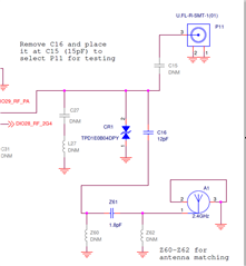
    I am testing rfDiagnostics on my LP-CC2651P3. On the board, I removed C16 and placed a 15pF cap at C15 to use the U.FL connector. I loaded the rfDiagnostics project (did not make any config or code changes). I entered the following commands to enable CW at 2.425GHz:

    AT+I 1
    ATPFR=2425000000
    ATPTM=0

    I also read the power level setting:

    ATPPW?
    5 dBm
    OK

    However, when I measure the output power I get +1.1dBm (3.9dBm too low). Any ideas?

    Thanks,
    Andy

  • You've gathered a basic understanding of AT commands.  You do not have to initialize ATPTM to zero, you can set to one for Carrier Wave mode followed by zero to reset.  Since you are using a LaunchPad, how does this same setup perform in Smart RF Studio?  Why did you choose a capacitor value of 15 pF and what are the results when evaluating High PA mode (enabled in the SysConfig -> Custom -> IEEE module)?

    Regards,
    Ryan

  • Hi Ryan,

    I tried Smart RF Studio and got the same results. Then I changed my RF cabling and now the measured power level is only 0.8dB below the setting. So that is good news that is was a cable issue.

    FYI the 15pF capacitor value came from the comment in the schematic:

  • Glad to hear the results have improved Slight smile

    Regards,
    Ryan

  • Hi Ryan,

    I'm now trying to build rfDiagnostics for our custom board. I used "switch device", which then allowed me to change the antenna switching GPIO configuration in the RF driver section. Now when I build I get the error "you_must_implement_rfDriverCallbackAntennaSwitching_see_generated_ti_drivers_config_c_in_debug_folder_or_sysconfig_preview ./syscfg/ti_drivers_config.o"

    which points me to the following code:

    void __attribute__((weak)) rfDriverCallbackAntennaSwitching(RF_Handle client, RF_GlobalEvent events, void *arg)
    {
    /* ======== PLEASE READ THIS ========
    *
    * This function is declared weak for the application to override it,
    * and the undefined function call below is intended to catch the
    * developer's attention at link time.
    * A new definition of 'rfDriverCallbackAntennaSwitching' is required.
    *
    * Please copy this function definition to create your own, but make
    * sure to remove '__attribute__((weak))' for your definition and
    * remove the below function declaration and function call.
    *
    * To handle the events listed in '.globalEventMask', please see the
    * help text provided in 'rfDriverCallback' above.
    *
    * For an example on how to interact with the selected antenna pins,
    * please see the code snippet below:
    *
    * --- Code snippet begin ---
    *
    * // > This assumes antenna switch pins have been added to GPIO via
    * // > sysconfig with the following properties:
    * // > mode: Output
    * // > initialOutputState: Low
    * // > outputStrength: High
    *
    * // > Set pin output value manually
    * GPIO_write(CONFIG_RF_24GHZ, 0); // Low
    * GPIO_write(CONFIG_RF_24GHZ, 1); // High
    *
    * // > Mux pin to be driven/controlled by the RF Core
    * // > (RFC GPIO0 is here only used as an example)
    * GPIO_setMux(CONFIG_RF_24GHZ, IOC_PORT_RFC_GPO0);
    *
    * // > Mux pin to be controlled manually (i.e. release RF Core control)
    * GPIO_setMux(CONFIG_RF_24GHZ, IOC_PORT_GPIO);
    *
    * --- Code snippet end ---
    */
    extern void you_must_implement_rfDriverCallbackAntennaSwitching_see_generated_ti_drivers_config_c_in_debug_folder_or_sysconfig_preview(void);
    you_must_implement_rfDriverCallbackAntennaSwitching_see_generated_ti_drivers_config_c_in_debug_folder_or_sysconfig_preview();
    }

    Now I have some questions. Do I need to control the antenna GPIO in firmware using:

    GPIO_write(CONFIG_RF_24GHZ, 0); // Low
    GPIO_write(CONFIG_RF_24GHZ, 1); // High

    or can I have it controlled by the RF core:

    GPIO_setMux(CONFIG_RF_24GHZ, IOC_PORT_RFC_GPO0);

    And, If I must control it in firmware I'm not sure how that is possible, since there is no RF_GlobalEvent for enabling/disabling the PA:

    typedef enum {
    RF_GlobalEventRadioSetup = (1 << 0), ///< The RF core is being reconfigured through a setup command.
    RF_GlobalEventRadioPowerDown = (1 << 1), ///< The RF core is being powered down.
    RF_GlobalEventInit = (1 << 2), ///< RF_open() is called for the first time (number of registered clients changes from 0 to 1).
    RF_GlobalEventCmdStart = (1 << 3), ///< A command chain is being dispatched to the radio.
    RF_GlobalEventCmdStop = (1 << 4), ///< Command termination event is handled.
    RF_GlobalEventCoexControl = (1 << 5), ///< Change to coex configuration is requested
    RF_GlobalEventTempNotifyFail = (1 << 6), ///< Registration of temperature notification was unsuccessful
    } RF_GlobalEvent;

    Thanks,
    Andy

  • Hi Andy,

    Since you are not using a LaunchPad design, you must include rfDriverCallbackAntennaSwitching inside your application.  The following code excerpt is copied from the default project ti_drivers_config.c:

    #include <ti/drivers/rf/RF.h>
    void __attribute__((weak)) rfDriverCallbackAntennaSwitching(RF_Handle client, RF_GlobalEvent events, void *arg)
    {
    
        if (events & RF_GlobalEventRadioSetup) {
            /* Switch off all paths. */
            GPIO_write(CONFIG_RF_HIGH_PA, 0);
            GPIO_write(CONFIG_RF_24GHZ, 0);
    
            /* Decode the current PA configuration. */
            RF_TxPowerTable_PAType paType = (RF_TxPowerTable_PAType)RF_getTxPower(client).paType;
    
            if (paType == RF_TxPowerTable_HighPA) {
                /*
                * Mux GPIOs to RF Core signals:
                * - High PA    --> HIGH PA
                * - LNA enable --> 2.4 GHz
                */
                GPIO_setMux(CONFIG_RF_HIGH_PA, IOC_PORT_RFC_GPO3);
                GPIO_setMux(CONFIG_RF_24GHZ, IOC_PORT_RFC_GPO0);
            } else {
                /* RF Core active --> 2.4 GHz   */
                GPIO_write(CONFIG_RF_24GHZ, 1);
            }
        }
        else if (events & RF_GlobalEventRadioPowerDown) {
            /* Switch off all paths. */
            GPIO_write(CONFIG_RF_24GHZ, 0);
            GPIO_write(CONFIG_RF_HIGH_PA, 0);
    
            /* Reset the IO multiplexer to GPIO functionality */
            GPIO_setMux(CONFIG_RF_24GHZ, IOC_PORT_GPIO);
            GPIO_setMux(CONFIG_RF_HIGH_PA, IOC_PORT_GPIO);
        }
    }

    Inserting this at the bottom of rfDiagnostics.c should allow your code to build.  You should not have to control antenna GPIO outside of setting the correct configurations for each event inside this function.  Pin selection and GPIO configuration, including "Value Inversion", is available from the SysConfig -> RF module.  You can also review relevant E2E threads on this topic.

    Regards,
    Ryan