Part Number: CC2651P3
Other Parts Discussed in Thread: SYSCONFIG, Z-STACK
We have a design based on CC2651P3, using the RKP package and +10dBm output level. This design was reviewed by TI from a hardware perspective
We are measuring the TX power from the PA. We are using the following PA table entry:
{10, RF_TxPowerTable_HIGH_PA_ENTRY(38, 1, 1, 39, 16) }, // 0x104F66
Using this entry, the actual PA output is around +3dBm (expected is +10dBm).
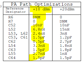
Note that in the CC2651P3 datasheet (and launchpad schematic), it shows that the PA path should be biased by VDDR when using +10dBm. And when using +20dBm, it is biased by VDDS. The launchpad by default is biased by VDDS, but it has an option to be biased by VDDR by moving R6 to position R7. Our design is biased by VDDR, because we are using +10dBm.
As a test, I checked to see how the launchpad would behave when its bias is changed from VDDS to VDDR. I used the +10dBm PA table entry shown above. When biased by VDDS the measured output power is +10dBm. When biased by VDDR the measured power is around +3dBm. So, I was able to reproduce the low TX power issue on launchpad.
It seems that when the PA is biased by VDDR it needs to be configured differently to work properly. However I have not been able to find any documentation on this. Please advise.
Regards,
Andy