This thread has been locked.

If you have a related question, please click the "Ask a related question" button in the top right corner. The newly created question will be automatically linked to this question.

CC2592EMK-RD: EVM issue of CC2520+CC2592

Part Number: CC2592EMK-RD
Other Parts Discussed in Thread: CC2520, CC2592, CC2530

Hello

One product of our company uses CC2520+CC2592 scenario for Zigbee function. This product has been released for several years. Recently,  many samples failed the EVM test in production test.

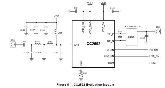
When I reviewed its design files and BOM, I found there are two differences between our design and CC2592 reference design. The below picture is the part of CC2592 SCH.
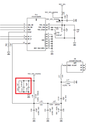
    

Differences:

1. C97(1uF) and C101(1nF) were not mounted on the board. 

2. The transmission (from CC2592 output to antenna) impedance is about 42 ohm.

So I have some questions about it.

Question:

1. If these two capacitors which are mounted on board will affect the EVM performance?

2. If the transmission line impedance which is not 50 ohm will affect the EVM performance?

3. Is there optimal load impedance for CC2592 PA? I don't find it on datasheet.

Thanks.

  • Hi,

    Thanks for your inquiry. I couldn't find a reference design for the pair CC2520 + CC2592, but I am using a very similar reference design (CC2530 + CC2592)

    With that in mind, I have a few comments:

    Since the issue started to happen after a very long production run, and assuming the parts being used during assembly do not have significant parameter variations, any specific design deviations from our reference do not seem to be a contributing factor to this, either the decoupling capacitors or an impedance mismatch. In your specific case I would probably look for other assembly and manufacturing aspects such as assembly materials (solder composition, solder paste, PCB copper density, etc.) or even contamination (out-of-spec humidity or improper handling, for example).

    Answering your questions:

    1) The decoupling capacitors can have a significant influence on the RF performance, either by reducing spurious or harmonics or both. However, since per your description the issue only started to happen recently, they might not be the contributing factor in this case. 

    2) The impedance mismatch will affect the performance, but the 42Ω you mentioned will not be very significant - certainly not a factor that would suddenly cause problems after so many years.

    3) The PA output impedance of our CC2592 is 50Ω.

    Just for your information, I am in a parallel discussion with other people regarding this issue, trying to investigate any other possible root causes for the current scenario.

    Hope this helps,

    Rafael

  • Hi Rafael,

    Thanks for your reply.

    In regards to the third answer, you mean the PA output impedance is internally matched to 50 ohm, right?  If it is, from the below picture, those components on the CC2592 output are not used for impedance matching, right?

    1. C101, C103, C105, L102, L103 are used for low pass filter.

    2. L101 is used for PA power supply and RF signal blocking.

    And other questions about CC2592 output power.

    1. For conform to the FCC limits, what is the maximum recommended output power of CC2592?

    2.  Is reducing outpower beneficial to improve EVM?

    Thanks.

  • Hi,

    the PA output impedance is internally matched to 50 ohm, right?

    Yes.

    If it is, from the below picture, those components on the CC2592 output are not used for impedance matching, right?

    In the CC2592 datasheet section 5, the table immediately below the picture you shared above contains the functions of all passive devices that comprise the reference design. In this case, the parts you mentioned perform the function of antenna matching and PA bias.

    1. For conform to the FCC limits, what is the maximum recommended output power of CC2592?

    There is no absolute answer to this question. The conformance to FCC limits requires simulations and test on your own hardware, both conducted and irradiated.

    That said, table 2.4 of the CC2592 Datasheet contains several performance characterization numbers of this device. The section RF Transmit of this table contains the conducted measurements, including output power, that had a passing FCC conducted limit - however, keep in mind these tests were made with the CC2592EM reference design being fed using a signal generator, not a device. Any deviations to this setup will require simulations and tests to be performed. As mentioned in this post, consult the CC2538-CC2592 EM Reference design for details.

    2.  Is reducing outpower beneficial to improve EVM?

    Potentially yes, but a quantifiable performance characteristic must be obtained using your system.

    All that said, unless there is a significant difference in the BOM or manufacturing (as I mentioned before) or on the CC2520 power output configuration, these design details do not seem related to a production problem as you described in your original post, therefore I would start investigating any variations there.

    Regards,

    Rafael

  • Hi Rafael,

    Thanks for your reply. We have done some EVM testing by using different CC2520 TX power set-up. I have some points to discuss with you. Please refer to the below table. These testing have be done in a shield chamber, radiated testing method. The frequency is 2405MHz.

    1. "no data" means that spectrum analyzer shows " carrier lock?" and can not get EVM data.

    2. In regards TX power, The TX power data of TXPOWER register value F7, F2, AB is larger than the TX power data of TXPOWER register value F9.

    So when the CC2520 TXPOWER register value is 0XF9, its output power is unlikely to be above +5dBm. I don't find the register value F9 on the datasheet. Could you please help to check this register value?

    3. The TX power data of TXPOWER register value 13 is almost the same with  the TX power data of TXPOWER register value F9. So when the CC2520 TXPOWER register value is 0XF9, its output power is probably to be +1dBm.

    4. When the CC2520 TXPOWER register value is 13, 32, 81, the samples have the better EVM data. 

      CC2520 TXPOWER register CC2520 TX power (dBm)   1 2 3
    1 0XF9 large than 5 offsetEVM 4.819363 3.135641 4.082448
    TX Power -23.253 -14.207 -19.459
    2 0XF7 5 offsetEVM no data no data no data
    TX Power -22.586 -13.658 -19.02
    3 0XF2 3 offsetEVM 23.431652 9.334433 no data
    TX Power -22.506 -13.648 -18.837
    4 0XAB 2 offsetEVM 7.78446 10.57768 no data
    TX Power -22.698 -13.765 -19.257
    5 0X13 1 offsetEVM 5.528691 6.914721 5.454413
    TX Power -23.381 -14.375 -19.712
    6 0X32 0 offsetEVM 5.149186 5.883844 6.422539
    TX Power -23.946 -14.913 -20.262
    7 0X81 -2 offsetEVM 5.452402 3.594562 8.601568
    TX Power -24.722 -15.776 -20.937
    8 0X88 -4 offsetEVM 7.541842 5.047617 26.565872
    TX Power -25.812 -16.87 -22.137
    9 0X2C -7 offsetEVM 22.227558 19.194666 14.70832
    TX Power -29.929 -20.191 -25.727
    10 0X3 -18 offsetEVM no data 12.912502 32.634113
    TX Power -44.105 -32.338 -38.745
  • Hi,

    There is a lot of information to unpack in this post, so I will need some time to distill all this and get back to you.

    A few comments:

    - I need to confirm a few details but, if the 0xF9 register value is not specified in our datasheet, it might be pushing the radio outside of its normal operation. Please stay within our datasheet specifications.

    - The Carrier Lock warning probably is warning you of excessive input power, but I can't be sure. An attenuator might be needed to get the signal compatible with your Spectrum Analyzer.

    I will get back to you as soon as I can get some additonal information.

    Regards,

    Rafael

  • Hi Rafael,

    I want to share a point with you.

    I have confirmed with Keysight support engineer that  " carrier lock?" means demodulation failure. And from the above table, the TX power is less than -10dBm, it doesn't look like excessive input power. 

    Is there any update from your side?

    Thanks.

  • Gavin,

    Thanks for the confirmation.

    Regarding your last point:

    When the CC2520 TXPOWER register value is 13, 32, 81, the samples have the better EVM data. 

    This is expected, since the lower output levels are near the noise floor and the upper levels can potentially have higher distortion.

    That said, after a closer look at your table I have a few questions:

    - How is the Tx power being exactly measured? Is this conducted or irradiated? The rows that have the "Tx Power" shows numbers very different than what would be expected either on the output of the CC2592 or the CC2520.
    - Are the measurements being done in the boards of the new production run? If so, what are the measurements in one of the prior boards?
    - What exactly is the failure? Are you expecting to get the EVM lower than 35% at 5 dBm of input power?

    All those details might not be important in the light of the recent manufacturing issues you are running - after all, your design seems to have worked for years before that, so any inherent designs problems would have been evidenced before. 

    Best regards,

    Rafael

  • Hi Rafael,

    My comments about your question.

    1. This product uses a chip antenna. We put the samples in a shield chamber and test it by radiated method. In fact, "TX Power" is the measurement of chip antenna radiated power.

    2. We don't do the board testing for new production run. We directly test the samples in the shield chamber.

    3. We can accept the EVM lower than 35% at a lower input power, such as 0dBm input power.

    4. Could you help to check what the CC2520 output power is, when the TXPOWER register is 0XF9?

    Thanks.