This thread has been locked.

If you have a related question, please click the "Ask a related question" button in the top right corner. The newly created question will be automatically linked to this question.

LP-CC1352P7: Basic project to transmit and receive an IEEE 802.15.4 frame

Part Number: LP-CC1352P7
Other Parts Discussed in Thread: SYSCONFIG

I need an example project(or help to create one using CCS) to be able to transmit and receive an 802.1.5.4 frame accessing radio core directly.

Not able to get proper details from the SDK and associated documentation.

Can somebody please guide me through this? Thanks a lot!

  • Hi Marie, thanks for responding.

    I did go through the example pointed. I wanted to get a deeper understanding of the source code.

    For example: I did not understand where this command is defined: CMD_PROP_RX and what other such commands are available to write custom code.

    Thanks

  • Additionally, I wanted to configure the radio to transmit and receive on a particular IEEE 802.15.4 channel

  • Hi Karthik,

    I would recommend you to use the RF driver.

    You can find all the RF driver documentation here: https://dev.ti.com/tirex/explore/content/simplelink_cc13xx_cc26xx_sdk_7_10_00_98/docs/rflib/html/index.html

    The CMD_PROP definitions are given here (click each command for details): https://dev.ti.com/tirex/explore/content/simplelink_cc13xx_cc26xx_sdk_7_10_00_98/docs/rflib/html/cc13x2__cc26x2_2driverlib_2rf__prop__cmd_8h.html 

    Cheers,

    Marie H

  • HI Marie,

    Managed to write a sample application for IEEE Rx mode.

    For IEEE Tx mode, unable to find a provision to configure channel number.

    Here is the code.The code crashes on executing RF_runCmd function.

    void *mainThread(void *arg0)
    {

        RF_Params rfParams;
        RF_Params_init(&rfParams);
        rfParams.nID = RF_STACK_ID_154;

        GPIO_setConfig(CONFIG_GPIO_GLED, GPIO_CFG_OUT_STD | GPIO_CFG_OUT_LOW);

        GPIO_write(CONFIG_GPIO_GLED, CONFIG_GPIO_LED_OFF);

        RF_cmdIeeeTx_ieee154p10_0.payloadLen = PAYLOAD_LENGTH;
        RF_cmdIeeeTx_ieee154p10_0.pPayload = packet;
        RF_cmdIeeeTx_ieee154p10_0.startTrigger.triggerType = TRIG_NOW;

        rfHandle = RF_open((RF_Object *)&rfObject, &RF_prop_ieee154p10_0, (RF_RadioSetup*) &RF_cmdRadioSetup_ieee154p10_0, &rfParams);

        RF_postCmd(rfHandle, (RF_Op*)&RF_cmdFs_ieee154p10_0, RF_PriorityNormal, NULL, 0);

        //Set the operating Channel
        //RF_cmdIeeeTx_ieee154p10_0.channel = 11;

        while(1)
        {
            /* Create packet with incrementing sequence number and random payload */
            packet[0] = (uint8_t)(seqNumber >> 8);
            packet[1] = (uint8_t)(seqNumber++);
            uint8_t i;
            for (i = 2; i < PAYLOAD_LENGTH; i++)
            {
                packet[i] = rand();
            }

            /* Send packet */
            RF_EventMask terminationReason = RF_runCmd(rfHandle, (RF_Op*)&RF_cmdIeeeTx_ieee154p10_0, RF_PriorityNormal, NULL, 0);

            GPIO_toggle(CONFIG_GPIO_GLED);

            /* Power down the radio */
            RF_yield(rfHandle);

            /* Sleep for PACKET_INTERVAL us */
            usleep(PACKET_INTERVAL);

        }

    Thanks

    Karthik

  • Hi Karthik,

    For channel, you need to change the frequency parameter of RF_cmdRadioSetup_ieee154p10_0 and RF_cmdFs_ieee154p10_0, check ti_radio_config.c generated by SysConfig as a reference. You will have to close/open the RF driver between channel changes.

    Use RF_runScheduleCmd instead of RF_runCmd if using an IEEE PHY.  https://e2e.ti.com/f/1/t/1002235 

    Regards,
    Ryan

  • Hi Ryan,

    Here is the structure.There is no frequency parameter in it or Am I missing something?

    // CMD_RADIO_SETUP_PA
    // Radio Setup Command for Pre-Defined Schemes
    rfc_CMD_RADIO_SETUP_PA_t RF_cmdRadioSetup_ieee154p10_0 =
    {
        .commandNo = 0x0802,
        .status = 0x0000,
        .pNextOp = 0,
        .startTime = 0x00000000,
        .startTrigger.triggerType = 0x0,
        .startTrigger.bEnaCmd = 0x0,
        .startTrigger.triggerNo = 0x0,
        .startTrigger.pastTrig = 0x0,
        .condition.rule = 0x1,
        .condition.nSkip = 0x0,
        .mode = 0x01,
        .loDivider = 0x00,
        .config.frontEndMode = 0x0,
        .config.biasMode = 0x1,
        .config.analogCfgMode = 0x0,
        .config.bNoFsPowerUp = 0x0,
        .config.bSynthNarrowBand = 0x0,
        .txPower = 0x762E,
        .pRegOverride = pOverrides_ieee154p10_0,
        .pRegOverrideTxStd = 0,
        .pRegOverrideTx20 = 0
    };

    The following structure has frequency parameter. How do I know what value to be written say for channel 12 or 13 or 14 etc( 802.15.4 channels)

    // CMD_FS
    // Frequency Synthesizer Programming Command
    rfc_CMD_FS_t RF_cmdFs_ieee154p10_0 =
    {
        .commandNo = 0x0803,
        .status = 0x0000,
        .pNextOp = 0,
        .startTime = 0x00000000,
        .startTrigger.triggerType = 0x0,
        .startTrigger.bEnaCmd = 0x0,
        .startTrigger.triggerNo = 0x0,
        .startTrigger.pastTrig = 0x0,
        .condition.rule = 0x1,
        .condition.nSkip = 0x0,
        .frequency = 0x0965,
        .fractFreq = 0x0000,
        .synthConf.bTxMode = 0x0,
        .synthConf.refFreq = 0x0,
        .__dummy0 = 0x00,
        .__dummy1 = 0x00,
        .__dummy2 = 0x00,
        .__dummy3 = 0x0000
    };

    Thanks

    Karthik

  • My initial reply was incorrect, frequency only applies to RF_cmdFs_ieee154p10_0 only andnot RF_cmdRadioSetup_ieee154p10_0 as well.  I've clarified my original post. 0x0965 is channel 11 and you can see the Generated files view of SysConfig to observe the different values as you modify the Channel from the IEEE module accordingly.

    Regards,
    Ryan

  • Thanks Ryan. This helped.

  • cc1352p4-4_tx_rx_test.zip

    Hi Ryan, please see the attached.

    Code for Tx and Rx ( used two lauchpad boards - one is Transmitter and the other Receiver).

    Transmitting data on channel 11 for every one second.

    I can see the green LED toggle on Transmitter every 1 second.

    I cannot see the red LED toggle on Receiver. On debug, I don't see the control switching to call back function.

    Kindly review the code and let me know if I am missing something.

    Thanks

  • Hi Karthik,

    Please test your PropRF code with Smart RF Studio 7 (one LaunchPad for each interface), meaning you should test the rfPacketTx project with Smart RF Studio receive mode and rfPacketRx with Smart RF Studio transmit mode.  A similar approach is described in the Basic RX and TX SimpleLink Academy Lab.  Then you may be able to determine whether the transmitter or receiver ends are not operating as expected, after which you can further determine whether there are any mismatched RF settings or the previous migration instructions have not been followed entirely.

    Regards,
    Ryan

  • Hi Ryan,

    I had tested with SmartRF( Tx and Rx) and was able to see packets on the receiver.

    Also tested, Firmware Tx and SmartRF Rx. Was able to see packets on one channel( example here is channel # 11).

    Was testing firmware Tx changing channels with packet length of 30 bytes. I am not able to see proper 15.4 based packets on SmartRF receiver. Mysteriously, it SmartRF captures packets on Channel 14/ Channel 20 even though the Firmware Tx is halted. Attached snapshots.

    Could you explain this phenomenon.

    Also, how to ensure that SmartRF Rx to receive just the intended packets on a configured channel while the Firmware Tx transmits across all 802.15.4 channels?

  • This test confirms an issue with your packet transmission project.  I suggest you clean/rebuild your project, check the radio settings, and consider importing a fresh project and apply the changes we discussed earlier.  The packets which you observe being received are from other nearby devices using 802.15.4 networking packets on the same channel and there is no way to filter these out inside of Smart RF Studio.

    Regards,
    Ryan

  • Ryan.

    I wonder if its the transmitter code. Like I mentioned, Firmware Tx is able to send packets and I am able to see the same on Smart RF receiver( on channel # 11).

    The issue is when I change channel number on every iteration ( to emulate channel hopping) and transmit, I am not able to see packets captured properly on SmartRF receiver.

    FYI: there are no nearby 802.1.5.4 devices in the vicinity. So, I still wonder how these packets are processed by Smart RF.

    Attached the transmitter code. Kindly review and appreciate your comments on it.rfPacketTx.zip

  • Thank you for clarifying the issue (i.e. frequency hopping).

    • You should cancel all existing/queued RF commands before changing channels
    • RF_cancelCmd and RF_flushCmd should be adequate to abort any RF activity
    • RF_pendCmd will return with RF_EventCmdCancelled, RF_EventCmdAborted, or RF_EventCmdStopped depending on the status of the command before cancel/flush was called.
    • Try adding a lengthy delay after the FS command to allow the frequency synthesizer to finalize changes

    After which the channel can be changed by using the CMD_FS command.  For easy reference and more specific details, here are links to the rflib APIs including RFCC26X2.h and Rf_driver.  Here is a relevant E2E post with proposed switching method: https://e2e.ti.com/f/1/t/1124734 

    Regards,
    Ryan

  • Hi Ryan, this information helped. I can see packets on SmartRF receiver by manually changing channels and monitoring.

    Have to verify with the firmware receiver.

    Could you please help how to output received packet data on CCS IDE's console terminal( while debugging the code)?

    Thanks

    Karthik

  • I recommend the Debug Printing SimpleLink Academy Lab or Display/UART2 TI Drivers (see display, uart2echo, or rfDiagnostics project examples).

    Regards,
    Ryan

  • The following header file is included : #include <ti/display/Display.h> 

    Re-used the code snippet from the tutorial:

    Display_Handle display;
    display = Display_open(Display_Type_HOST, NULL);


    Compilation throws errors. What else should I check?

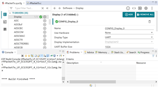
  • Did you add Display module from within the SysConfig file's TI DRIVERS options? I could recreate your project's behavior by leaving this out, but re-building with a Display module resolved the issue and completed the build.

    Regards,
    Ryan

  • Compilation is fine.

    Here is the initialisation code:

    Display_Handle display;

    Display_Params    params;

    //display = Display_open(Display_Type_HOST, NULL);

    display = Display_open(Display_Type_UART, &params);

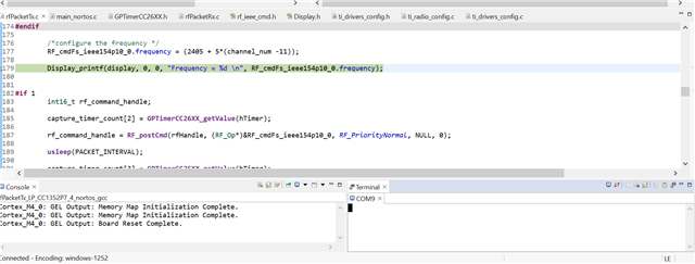
    Nothing gets printed on the CCS console(display type as HOST in sysconfig).

    Neither on CCS Terminal @ 115200 baud( when display type is UART in sysconfig).

    Anything else to cross check?

    Thanks

    Karthik

  • Did you change the SysConfig -> UART2 module's "Use Hardware" feature from "None" to "XDS110 UART"?  That worked for my system using the default LaunchPad's XDS110 backchannel UART connection.

    Note that I am using a different LaunchPad version (one with only 2.4 GHz) but still the rfPacketTx example so the concept applies.

    Regards,
    Ryan

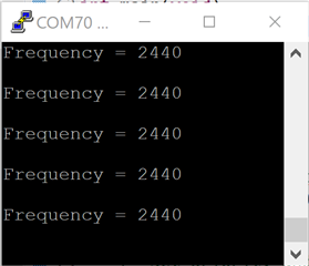
  • This worked!

    Thanks

    Karthik

  • Hi Ryan,

    Looks like Display_printf can only send data from target board to Terminal and also conflicts with UART APIs.

    Tried the uart2echo.c example. Changed the input buffer to hold 2 bytes. Could not see any bytes from the terminal.

    I would also like to type characters on the Terminal and the data to be read on the target board ( bi directional communication).

    Kindly suggest how to go about this.

    Thanks

    Karthik

  • You are correct that the UART TI Driver will need to be used as compared to the Display for bi-directional communication.  Here is a link to the TI Drivers Runtime APIs for further review.

    Tried the uart2echo.c example. Changed the input buffer to hold 2 bytes. Could not see any bytes from the terminal.

    What input buffer did you change?  I recommend that you get the default example to work as expected before attempting to make changes.  You should also review the examples provided in the TI Drivers documentation I linked.

    Regards,
    Ryan

  • Default example works fine. This is not sufficient to me. Will have to write my own printf function to output/read data to and from the Terminal.

    I changed "input" ( char type variable in uart2echo.c example) to hold two characters to see if it  captures whatever is typed on the Terminal.

    Also,not able to see update on bytesRead or bytesWritten variables( in the "Expressions" window).

    Thanks

    Karthik

  • bytesRead and bytesWritten initialization is not defined for multiple bytes, essentially you will need to use array instead.  Please consider studying the rfDiagnostics example's UART implementation (bi-directional).

    Regards,

    Ryan

  • Thanks for sharing the documentation. I am not looking for AT command implementation.

    A simple UART based transfer to write to the Terminal and read from the terminal.

    For example, I tried this for printing data on the Terminal and it worked. I still did not understand bytesWritten parameter though.

    void uart_printf(const char *format, ...)
    {
        va_list args;
        va_start(args, format);

        char buffer[128];
        vsnprintf(buffer, sizeof(buffer), format, args);

        va_end(args);

        uart_send_data((const uint8_t *)buffer, strlen(buffer));
    }

    void uart_send_data(const uint8_t *data, uint32_t len)
    {
        size_t bytesWritten = 0;
        UART2_write(uart, data, len,&bytesWritten); // UART API from TI drivers
    }

    uart_printf("Integer value: %d\r\n", value_int);
    uart_printf("Floating-point value: %.2f\r\n", value_float);

    Similarily, I need a function to handle reading data from terminal. In this case, special handling is needed to handle user input.The user can type proper data and hit "Enter" OR may type something wrong, enter backspace to correct it and then press "Enter".

    Thanks

    Karthik

  • Here are the routines that worked for me:

    The following function can read data from Terminal:

    void uart_read_data(void)
    {
        char input;
        size_t bytesRead;
        size_t bytesWritten = 0;
        uint32_t status     = UART2_STATUS_SUCCESS;

        while (1)
        {
            bytesRead = 0;
            while (bytesRead == 0)
            {
                status = UART2_read(uart, &input, 1, &bytesRead);

                if (status != UART2_STATUS_SUCCESS)
                {
                    /* UART2_read() failed */
                    while (1) {}
                }
            }

            uart_rx_buffer[i] = input;

            if (uart_rx_buffer[i]  > 0) {
                // Character received
                if (uart_rx_buffer[i] == '\r') {
                    // Carriage return (Enter key)
                    uart_rx_buffer[i] = '\0'; // Null-terminate the buffer
                    uart_printf("\r\n"); // Echo new line
                    break;
                }
                else if (uart_rx_buffer[i] == '\b' || uart_rx_buffer[i] == 0x7F) {
                    // Backspace or DEL key
                    if (i > 0) {
                        i--;
                    }
                }
                else if(i< UART_BUFFER_SIZE -1) {
                    // Normal character
                    bytesWritten = 0;
                    while (bytesWritten == 0)
                    {
                        status = UART2_write(uart, &input, 1, &bytesWritten);

                        if (status != UART2_STATUS_SUCCESS)
                        {
                            /* UART2_write() failed */
                            while (1) {}
                        }
                    }
                    i++;
                }
            }


        }
    }

    The following functions can output prints to the console:

    // Function to send data through UART
    void uart_send_data(const uint8_t *data, uint32_t len)
    {
        size_t bytesWritten = 0;
        UART2_write(uart, data, len,&bytesWritten);
    }


    //Custom printf function for UART output
    void uart_printf(const char *format, ...)
    {
        va_list args;
        va_start(args, format);

        char buffer[128]; // Adjust buffer size as needed
        vsnprintf(buffer, sizeof(buffer), format, args);

        va_end(args);

        uart_send_data((const uint8_t *)buffer, strlen(buffer));
    }

    Example to test:

    int value_int = 42;
    float value_float = 3.14;

    /* Create a UART where the default read and write mode is BLOCKING */
        UART2_Params_init(&uartParams);
        uartParams.baudRate = 115200;

        uart = UART2_open(CONFIG_UART2_0, &uartParams);

        if (uart == NULL)
        {
            /* UART2_open() failed */
            while (1) {}
        }

    uart_printf("Hello, this is a UART printf example!\r\n");
    uart_printf("Integer value: %d\r\n", value_int);
    uart_printf("Floating-point value: %.2f\r\n", value_float);
    while(1);