This thread has been locked.

If you have a related question, please click the "Ask a related question" button in the top right corner. The newly created question will be automatically linked to this question.

CC2652R: Custom board goes to unknown state after uploading the code.

Part Number: CC2652R

Tool/software:

Hello everyone,

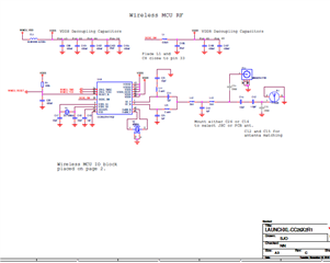
I am created custom board for CC2652R1F Microcontroller. The board seems to work fine to upload the code using XDS110 Debugger probe. However the Debugger cannot connect to DAP after uploading the script. Also I tried simple timer led example available in cc26x1 SDK. The pin does not toggle after upload or power cycle the board. Can someone help me asap? 

Cortex_M4_0: GEL Output: Memory Map Initialization Complete.
Cortex_M4_0: GEL Output: Board Reset Complete.
Cortex_M4_0: Error: (Error -1170 @ 0x0) Unable to access the DAP. Reset the device, and retry the operation. If error persists, confirm configuration, power-cycle the board, and/or try more reliable JTAG settings (e.g. lower TCLK). (Emulation package 12.8.0.00189)
Cortex_M4_0: Trouble Halting Target CPU: (Error -2064 @ 0x0) Unable to read device status. Reset the device, and retry the operation. If error persists, confirm configuration, power-cycle the board, and/or try more reliable JTAG settings (e.g. lower TCLK). (Emulation package 12.8.0.00189)
Cortex_M4_0: Error: (Error -1170 @ 0x0) Unable to access the DAP. Reset the device, and retry the operation. If error persists, confirm configuration, power-cycle the board, and/or try more reliable JTAG settings (e.g. lower TCLK). (Emulation package 12.8.0.00189)

  • Hi,

    Check to see if the target config .xml file is updated.
    also check this link for debugging JTAG issues. Debugging JTAG

    Regards,

  • Hello FI,

    Thanks for reply. What specific settings needs to updated? I have pasted the target test connection results and the snapshot of target congig. let me know what should needs to be changed. 

    Test Connection Log:

    [Start: Texas Instruments XDS110 USB Debug Probe]

    Execute the command:

    %ccs_base%/common/uscif/dbgjtag -f %boarddatafile% -rv -o -S integrity

    [Result]


    -----[Print the board config pathname(s)]------------------------------------

    C:\Users\navee\AppData\Local\TEXASI~1\CCS\
    ccs1280\0\0\BrdDat\testBoard.dat

    -----[Print the reset-command software log-file]-----------------------------

    This utility has selected a 100/110/510 class product.
    This utility will load the adapter 'jioxds110.dll'.
    The library build date was 'Jul 24 2024'.
    The library build time was '18:57:55'.
    The library package version is '12.8.0.00189'.
    The library component version is '35.35.0.0'.
    The controller does not use a programmable FPGA.
    The controller has a version number of '5' (0x00000005).
    The controller has an insertion length of '0' (0x00000000).
    This utility will attempt to reset the controller.
    This utility has successfully reset the controller.

    -----[Print the reset-command hardware log-file]-----------------------------

    The scan-path will be reset by toggling the JTAG TRST signal.
    The controller is the XDS110 with USB interface.
    The link from controller to target is direct (without cable).
    The software is configured for XDS110 features.
    The controller cannot monitor the value on the EMU[0] pin.
    The controller cannot monitor the value on the EMU[1] pin.
    The controller cannot control the timing on output pins.
    The controller cannot control the timing on input pins.
    The scan-path link-delay has been set to exactly '0' (0x0000).

    -----[Perform the Integrity scan-test on the JTAG IR]------------------------

    This test will use blocks of 64 32-bit words.
    This test will be applied just once.

    Do a test using 0xFFFFFFFF.
    Scan tests: 1, skipped: 0, failed: 0
    Do a test using 0x00000000.
    Scan tests: 2, skipped: 0, failed: 0
    Do a test using 0xFE03E0E2.
    Scan tests: 3, skipped: 0, failed: 0
    Do a test using 0x01FC1F1D.
    Scan tests: 4, skipped: 0, failed: 0
    Do a test using 0x5533CCAA.
    Scan tests: 5, skipped: 0, failed: 0
    Do a test using 0xAACC3355.
    Scan tests: 6, skipped: 0, failed: 0
    All of the values were scanned correctly.

    The JTAG IR Integrity scan-test has succeeded.

    -----[Perform the Integrity scan-test on the JTAG DR]------------------------

    This test will use blocks of 64 32-bit words.
    This test will be applied just once.

    Do a test using 0xFFFFFFFF.
    Scan tests: 1, skipped: 0, failed: 0
    Do a test using 0x00000000.
    Scan tests: 2, skipped: 0, failed: 0
    Do a test using 0xFE03E0E2.
    Scan tests: 3, skipped: 0, failed: 0
    Do a test using 0x01FC1F1D.
    Scan tests: 4, skipped: 0, failed: 0
    Do a test using 0x5533CCAA.
    Scan tests: 5, skipped: 0, failed: 0
    Do a test using 0xAACC3355.
    Scan tests: 6, skipped: 0, failed: 0
    All of the values were scanned correctly.

    The JTAG DR Integrity scan-test has succeeded.

    [End: Texas Instruments XDS110 USB Debug Probe]

  • Hi,

    JTAG seems alright from the log you sent. Have you tried flashing an example code from the SDK?

    Regards,

  • Yes, It flashes alright, But the MCU does not run once you power cycle or reset the board. For example if I upload timerled example from SDK. It will upload fine. The following error will pop up in the console and also The defined Pin won't get high and low as in the example.

    Cortex_M4_0: Can't Run Target CPU: (Error -2134 @ 0x0) Unable to control device execution state. Reset the device, and retry the operation. If error persists, confirm configuration, power-cycle the board, and/or try more reliable JTAG settings (e.g. lower TCLK). (Emulation package 12.8.0.00189)
    Cortex_M4_0: Error: (Error -1170 @ 0x0) Unable to access the DAP. Reset the device, and retry the operation. If error persists, confirm configuration, power-cycle the board, and/or try more reliable JTAG settings (e.g. lower TCLK). (Emulation package 12.8.0.00189)
    Cortex_M4_0: Unable to determine target status after 20 attempts
    Cortex_M4_0: Failed to remove the debug state from the target before disconnecting. There may still be breakpoint op-codes embedded in program memory. It is recommended that you reset the emulator before you connect and reload your program before you continue debugging

  • Hi,

    I was asked to provide some insights in this thread.

    The issue you are seeing may indicate two possible causes:

    Either the code is causing your device to be inaccessible and/or unstable - perhaps due to instabilities with clock/power or other external factors such as a pin inadvertently asserted, causing problems with power faults, for example.

    Perhaps the JTAG TCLK speed may be too high for your custom hardware - this can be caused for very long JTAG connections that cause it to be severely unreliable.

    This and other details are provided in the Debugging JTAG page below - search for the error code (1170)

    https://software-dl.ti.com/ccs/esd/documents/ccs_debugging_jtag_connectivity_issues.html

    Hope this helps,

    Rafael

  • Hello Dedouza,

    Thank you for the reply. I have used the lowest TCLK speed as 100khz. It also uploads the code fine. But provides the same error. I am also closely following the TI design schematics as well.

    For the JTAG cable I am using 150 mm 10 Position standard Cable Assembly. Do you think it is too long?

  • I have used this schematic with ABS07-32.768KHZ-7-T clock and ABM12W-48.0000MHZ-7-D1X-T3 clock. Those models are different manufacturers than mentioned in the EVAL BOM. Let me know these clock modules are compatible ? 

  • Hi,

    The 100kHz clock might not be the most reliable due to other factors outside of the debug subsystem - I would set to to 1MHz minimum. You could also try using OSCAN1 which is less stringent. The 150mm cable might be borderline to a proper operation, but the TCLK reduction would minimize this.

    Regardless of these factors, my strongest suspicion is with the code failing to properly initialize the device.

    After uploading the code, does it automatically run to main()?If so, then the device is stable after its initialization and the debugging would be easier to be performed, as it belongs to your code.

    Otherwise, you would need to track where is the failure in the code between the entry point _c_int00 and the main(). Several e2e threads talk about this, but essentially you would have to disable the option to do auto run to main, launch the debugger and perform a step-by-step debug of your code.

    Check the post below for some references.

    https://e2e.ti.com/support/tools/code-composer-studio-group/ccs/f/code-composer-studio-forum/808058/ccs-cc2640r2f-unable-to-access-the-dap/2999640#2999640

    Hope this helps,

    Rafael

  • I have used this schematic with ABS07-32.768KHZ-7-T clock and ABM12W-48.0000MHZ-7-D1X-T3 clock. Those models are different manufacturers than mentioned in the EVAL BOM. Let me know these clock modules are compatible ? 

    The schematics are too low resolution, but the crystals seem to meet the specifications shown in section 8.14.3 of the CC2652R datasheet.

  • Hello Rafael,

    The microcontroller won't show any sign of running state after uploading the code. I have tested the script it runs well in the eval board. But I can't debug in custom board.  because it says it can't connect to the core after uploading. 

    Cortex_M4_0: Can't Run Target CPU: (Error -2134 @ 0x0) Unable to control device execution state. Reset the device, and retry the operation. If error persists, confirm configuration, power-cycle the board, and/or try more reliable JTAG settings (e.g. lower TCLK). (Emulation package 12.8.0.00189).

    I have also tested shorter 50mm JTAG cables and 1Mhz JTAG TCLK. It gives the same above error. I can't get it to running state.

  • Hello team,

    Thank you everyone for your responses. This issue is solved, i figured that inductor for the internal DC to DC converter is little smaller for my custom board. So I disabled internal the DC to DC converter after that the controller worked perfectly. I will later mount larger inductor and test the DC to DC converter.