This thread has been locked.

If you have a related question, please click the "Ask a related question" button in the top right corner. The newly created question will be automatically linked to this question.

Does ground reflection have huge effect on CC2530??

Other Parts Discussed in Thread: CC2531, CC2530, CC2591, CC1190, CC1101, CC1120

Hi, all.

Does ground reflection have huge effect on CC2530?? I am wondering if any measurement has been taken in TI regarding the performance of CC2530/CC2531 when using them quite near the ground, say 20-30cm height from the it. 

I used two CC2530 modules to communication with each other at 4dBm transmission power with the SMA antenna. Then I found them lost the communication at a distance of about 30 meters. And it became worse when using CC2531 dongles (with PCB antenna) which gave a communication range of only 15 meters. Those measurements were taken in a flat open area with concrete road and lawn and the modules were put 20-30cm from the ground. I think that is due to the ground reflection/deflection that ruins the communication. Does anyone have any idea of this phenomenon??

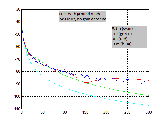
Although TI claims that CC2530/CC2531 can reach a range of about 450 meters. But those measurements were taken in a way that the modules were placed at least 1 meter from the ground when I watched the videos. 1 meter is quite long when comparing with the wavelength of 2.45GHz, so the ground reflection may not have much effect on the modules. In my application, however, some modules will be put at that height of around 20-30cm. So do you think I can still use CC2530/CC2531 in my case? What if I apply CC2591, the power amplifier in my system? Do you think that will help to reach hundreds meters range in my situation? Or do you think I should find some other alternatives instead of CC2530/CC2531? What is your idea of that?

Thank you very much!

  • JinKang, 

    We have an appnote discussion this topic including a simple Matlab script to simulated the performance.

    http://www.ti.com/lit/an/swra169a/swra169a.pdf

    So datasheet for CC2530, but you need some margin for multipath fading. Some say 10dB some say 20dB. Lets go with 10dB. From this I estimate 75 meters at 0.3m off the ground, 150meter at 1m off the ground, and 250meter at 3m and 10m off the ground.

    As the car industry says - mileage will vary based on conditions, please use these numbers with caution.

    Regards,
    /TA 

  • Thanks TA.

    That explains my observation. So if ground reflection has that much effect on the radio performance, what do you think I should do to get 100 meter range?

    In my application, the transceivers will be placed at 20-30cm off the ground which is a must. I could see two options: 1. use CC2591 power amplifier, 2. choose other solutions at 800-900MHz. Which do you think will much guarantee  the performance?

  • Jinkang, 

    Sub1Ghz (868MHz (EU) and 915(US)) is very popular for exactly the reason of getting range. Say you use a CC1190 range extender, you get approximately 120dB link budget. Then subtract the same 10dB as before and you have to use the 110dB point on this curve and you end up at 700 meters.

    If you cannot afford the extra transmit power of a CC1101+CC1190 combo, I would suggest a standalone CC1120 at low data rates. This device with get -120dB link budget without range extender but the datarate becomes low ( <10kbps)

    Regards,
    /TA 

  • TA, the ground reflection is basically the multipath effect issue? I made some simple estimation and I think for zigbee Baseband 250kbps(2M chip rate), there should not be significant ISI issue. so multipath should not be a big problem.

    please correct me if I am wrong.

    Rui

  • Rui, 

    The fades are actually bigger and can in most case attenuate an entire Zigbee channel. Some time ago we published a paper on this topic including some real life measurements. You might find this interesting.

    http://low-powerwireless.com/blog/designarticles/frequency-hopping-diversity-improves-low-power-wireless-system-performance/

    Regards,
    /TA 

  • TA, Thanks, I will take a look at your post.

    please see my calculation, 2M bps in chiprate , so the symbol period is 1/2M = 0.5us. for a serious ISI, the coherence time should be larger than 0.5us. which means the difference of arrival signal should be 0.5*10^(-6)*3*10^(8) = 150m. dose ground reflection casue so large difference?

    Also I don't quiet understand why sub 1G can solve multipath issue. it is only carrier frequncy change, not base bandwidth change(or sub 1G has less 250bps rate or less than 2M chip rate?).

    Thanks

    Rui 

  • Hi, TA

    Is there any Sub1GHz solution which gives at least 100kbps data rate while having a good range in my situation, I mean the near ground placement?

    What about using CC2591 together with CC2530, which gives 18dBm TX power extra?? I have started with CC2530 for a long time, so I prefer to make some usage of it. 

    At least 100kbps data rate, 100 meters range are my primary requirements. 

    Thank you for your information

  • Rui, 

    It is not ISI but rather just a fade. The signal drops below the receiver sensitivity level and the packets are dropped.

    Regards,
    /TA 

  • Jinkang,

    If your target is 100meters, a CC2530+CC2591 combo should work just fine. I believe it should be fine, but please make sure that you allowed to transmit at those power levels in the countries you are targeting. 

    Regards,

    /TA 

  • Hi Jinkang

    if you just require 100m and 100kbps, that should be fine. Also increasing TX power by CC2591 should not solving any multi path problem. Maybe your problem is not at multi path side, but rather in tx range side. in this case, sub 1G is better.

    Rui 

  • Hi, TA and Rui

    It has been a late followup. Thank you for your recommendations. 

    When I did the calculation according to the article on ranging measurement from TI (http://www.ti.com/lit/an/swra169a/swra169a.pdf), the fading was like 40dB for lawn area. Do you think it reasonable?? Do you think the RF signal would be coupled to the ground when the transceiver is placed near the ground?

    Anyway, now I am going for sub-1GHz solutions, hopefully they would work. Usually those transceivers have been built for different frequency bands, such as 433, 868 and 915 MHz. But we know that for different bands there should be different lengths for a proper antenna. I am wondering what TI recommends for the solutions on antenna design if we want to have the same setup on hardware for different countries? I mean, when we sell our products in different countries, we want to make no (or the least) change on the hardware.

    Thank you!

  • Jinkang, 

    The answers depends more on regions where you want to operate than physics. They are all good choices, but for operation in the US the 915MHz band is obvious choice. 868MHz or 433 in Europe.

    Regards,
    /TA 

  • TA,

    This I understood. But how about antenna? The antenna design should aim for different central frequencies when designing the PCBs for different regions. if I want to keep the same PCB in different regions to reduce the cost, does it mean I cannot use PCB antenna in my design?

  • Yes and no, 

    Please have a look at what we did on the value line reference design.

    http://www.ti.com/tool/cc110lem-868-915-rd

    We can change the band of operation by changing a matching component on the PCB, but the antenna stays the same.

    Regards,
    /TA